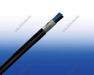
0.6/1kV XLPE Insulated, LSZH Sheathed Armoured CPR approved Power Cables to BS 6724(2-5 Cores)
FTX400 1RZ1MZ1-R (CU/XLPE/LSZH/SWA/LSZH 600/1000V Class 2) 


Applications
BS 6724 600/1000V XLPE Insulated, LSZH Sheathed CPR approved Power Cables aremainly used in power stations, mass transit underground passenger systems, airports,
petrochemical plants, hotels, hospitals and high-rise buildings.
Standard
Basic design to BS 6724
FIRE PERFORMANCE
| Flame Retardance (Single vertical wire or cable test) |
IEC 60332-1-2; EN 60332-1-2 |
| Reduced Fire Propagation (Vertically-mounted bundled wires & cables test) |
IEC 60332-3-24; EN 60332-3-24 |
| Halogen Free |
IEC 60754-1; EN 50267-2-1 |
| No Corrosive Gas Emission |
IEC 60754-2; EN 50267-2-2 |
| Minimum Smoke Emission |
IEC 61034-2; EN 61034-2 |
| CPR Compliance |
Eca |
Voltage Rating
600/1000V
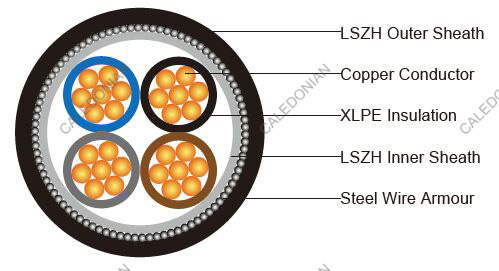
Construction
| Conductor |
Annealed copper wire, stranded according to BS EN 60228 class 2. |
| Insulation |
XLPE type GP8 according to BS 7655-1.3. HEPR type GP6 according to BS 7655-1.2 or
crosslinked polyolefin material type EI 5 according to BS EN 50363-5 can be offered as option. |
| Bedding: |
Extruded layer of polymeric material. |
| Armouring: |
Galvanized steel wire. |
| Outer Sheath: |
Extruded layer of polymeric material LTS 1 according to BS 7655-6.1. |
| Outer Sheath Option |
UV resistance, hydrocarbon resistance, oil resistance, anti-rodent and anti-termite
properties can be offered as option. |
Colour Code
| Insulation Colour |
2-core: Brown and blue.
3-core: Brown, black and grey.
4-core: Blue, brown, black and grey.
5-core: Green and yellow, blue, brown, black, grey. |
| Sheath Colour |
Black; other colours can be offered upon request. |
PHYSICAL AND THERMAL PROPERTIES
| Maximum temperature range during operation: |
90°C |
| Maximum short circuit temperature (5 Seconds): |
250°C |
| Minimum bending radius: |
8 × Overall Diameter |
CONSTRUCTION PARAMETERS
| Conductor |
FTX400 1RZ1MZ1-R |
| No. of Cores × Cross-sectional
Area |
Conductor Class |
Nominal Insulation Thickness |
Nominal Bedding Thickness |
Nominal Steel Wire Armour Diameter |
Nominal Sheath Thickness |
Approx. Overall Diameter |
Approx. Weight |
| No.×mm² |
|
mm |
mm |
mm |
mm |
mm |
kg/km |
| 2 Cores |
| 2×1.5a |
2 |
0.6 |
0.8 |
0.9 |
1.3 |
12.1 |
294 |
| 2×2.5a |
2 |
0.7 |
0.8 |
0.9 |
1.4 |
13.6 |
354 |
| 2×4a |
2 |
0.7 |
0.8 |
0.9 |
1.4 |
14.7 |
420 |
| 2×6a |
2 |
0.7 |
0.8 |
0.9 |
1.4 |
15.9 |
497 |
| 2×10a |
2 |
0.7 |
0.8 |
0.9 |
1.5 |
18.0 |
650 |
| 2×16a |
2 |
0.7 |
0.8 |
1.25 |
1.5 |
20.4 |
964 |
| 2×25a |
2 |
0.9 |
0.8 |
1.25 |
1.6 |
24.1 |
1314 |
| 2×25b |
2 |
0.9 |
0.8 |
1.25 |
1.6 |
20.4 |
1254 |
| 2×35a |
2 |
0.9 |
1.0 |
1.6 |
1.7 |
27.7 |
1832 |
| 2×35b |
2 |
0.9 |
1.0 |
1.6 |
1.7 |
23.3 |
1736 |
| 2×50b |
2 |
1.0 |
1.0 |
1.6 |
1.8 |
25.8 |
2261 |
| 2×70b |
2 |
1.1 |
1.0 |
1.6 |
1.9 |
29.0 |
2922 |
| 2×95b |
2 |
1.1 |
1.2 |
2.0 |
2.0 |
33.1 |
4029 |
| 2×120b |
2 |
1.2 |
1.2 |
2.0 |
2.1 |
36.1 |
4796 |
| 2×150b |
2 |
1.4 |
1.2 |
2.0 |
2.2 |
39.3 |
5646 |
| 2×185b |
2 |
1.6 |
1.4 |
2.5 |
2.4 |
44.7 |
7365 |
| 2×240b |
2 |
1.7 |
1.4 |
2.5 |
2.5 |
49.0 |
9027 |
| 2×300b |
2 |
1.8 |
1.6 |
2.5 |
2.6 |
53.5 |
10832 |
| 2×400b |
2 |
2.0 |
1.6 |
2.5 |
2.8 |
59.0 |
13216 |
| 3 Cores |
| 3×1.5a |
2 |
0.6 |
0.8 |
0.9 |
1.3 |
12.6 |
320 |
| 3×2.5a |
2 |
0.7 |
0.8 |
0.9 |
1.4 |
14.1 |
401 |
| 3×4a |
2 |
0.7 |
0.8 |
0.9 |
1.4 |
15.3 |
487 |
| 3×6a |
2 |
0.7 |
0.8 |
0.9 |
1.4 |
16.6 |
588 |
| 3×10a |
2 |
0.7 |
0.8 |
1.25 |
1.5 |
19.5 |
906 |
| 3×16a |
2 |
0.7 |
0.8 |
1.25 |
1.6 |
21.6 |
1190 |
| 3×25a |
2 |
0.9 |
1.0 |
1.6 |
1.7 |
26.7 |
1858 |
| 3×25b |
2 |
0.9 |
1.0 |
1.6 |
1.7 |
23.6 |
1755 |
| 3×35a |
2 |
0.9 |
1.0 |
1.6 |
1.8 |
29.4 |
2298 |
| 3×35b |
2 |
0.9 |
1.0 |
1.6 |
1.8 |
25.7 |
2154 |
| 3×50b |
2 |
1.0 |
1.0 |
1.6 |
1.8 |
28.5 |
2858 |
| 3×70b |
2 |
1.1 |
1.0 |
1.6 |
1.9 |
32.2 |
3761 |
| 3×95b |
2 |
1.1 |
1.2 |
2.0 |
2.1 |
37.0 |
5204 |
| 3×120b |
2 |
1.2 |
1.2 |
2.0 |
2.2 |
40.4 |
6258 |
| 3×150b |
2 |
1.4 |
1.4 |
2.5 |
2.3 |
45.5 |
7989 |
| 3×185b |
2 |
1.6 |
1.4 |
2.5 |
2.4 |
49.8 |
9586 |
| 3×240b |
2 |
1.7 |
1.4 |
2.5 |
2.6 |
55.1 |
11930 |
| 3×300b |
2 |
1.8 |
1.6 |
2.5 |
2.7 |
60.2 |
14427 |
| 3×400b |
2 |
2.0 |
1.6 |
2.5 |
2.9 |
66.6 |
17765 |
| 4 Cores |
| 4×1.5a |
2 |
0.6 |
0.8 |
0.9 |
1.3 |
13.3 |
388 |
| 4×2.5a |
2 |
0.7 |
0.8 |
0.9 |
1.4 |
15.0 |
460 |
| 4×4a |
2 |
0.7 |
0.8 |
0.9 |
1.4 |
16.4 |
566 |
| 4×6a |
2 |
0.7 |
0.8 |
1.25 |
1.5 |
18.7 |
813 |
| 4×10a |
2 |
0.7 |
0.8 |
1.25 |
1.5 |
21.1 |
1073 |
| 4×16a |
2 |
0.7 |
0.8 |
1.25 |
1.6 |
23.4 |
1431 |
| 4×25a |
2 |
0.9 |
1.0 |
1.6 |
1.7 |
28.9 |
2239 |
| 4×25b |
2 |
0.9 |
1.0 |
1.6 |
1.7 |
26.1 |
2102 |
| 4×35a |
2 |
0.9 |
1.0 |
1.6 |
1.8 |
31.9 |
2797 |
| 4×35b |
2 |
0.9 |
1.0 |
1.6 |
1.8 |
28.6 |
2606 |
| 4×50b |
2 |
1.0 |
1.0 |
1.6 |
1.9 |
32.0 |
3530 |
| 4×70b |
2 |
1.1 |
1.2 |
2.0 |
2.1 |
37.7 |
5074 |
| 4×95b |
2 |
1.1 |
1.2 |
2.0 |
2.2 |
41.7 |
6474 |
| 4×120b |
2 |
1.2 |
1.4 |
2.5 |
2.3 |
47.1 |
8390 |
| 4×150b |
2 |
1.4 |
1.4 |
2.5 |
2.4 |
51.4 |
9947 |
| 4×185b |
2 |
1.6 |
1.4 |
2.5 |
2.6 |
56.6 |
12096 |
| 4×240b |
2 |
1.7 |
1.6 |
2.5 |
2.7 |
63.0 |
15109 |
| 4×300b |
2 |
1.8 |
1.6 |
2.5 |
2.9 |
68.8 |
18276 |
| 4×400b |
2 |
2.0 |
1.8 |
3.15 |
3.2 |
78.1 |
23849 |
| 5 Cores |
| 5×1.5a |
2 |
0.6 |
0.8 |
0.9 |
1.4 |
14.3 |
413 |
| 5×2.5a |
2 |
0.7 |
0.8 |
0.9 |
1.4 |
16.1 |
521 |
| 5×4a |
2 |
0.7 |
0.8 |
0.9 |
1.5 |
17.8 |
658 |
| 5×6a |
2 |
0.7 |
0.8 |
1.25 |
1.5 |
20 |
932 |
| 5×10a |
2 |
0.7 |
0.8 |
1.25 |
1.6 |
22.9 |
1258 |
| 5×16a |
2 |
0.7 |
1.0 |
1.6 |
1.7 |
26.6 |
1893 |
| 5×25a |
2 |
0.9 |
1.0 |
1.6 |
1.8 |
31.5 |
2646 |
| 5×35a |
2 |
0.9 |
1.0 |
1.6 |
1.9 |
34.8 |
3326 |
| 5×50a |
2 |
1.0 |
1.2 |
2 |
2 |
40.4 |
4567 |
| 5×70a |
2 |
1.1 |
1.2 |
2 |
2.2 |
46.3 |
6056 |
a Circular or compacted circular stranded conductors (class 2).
b Shaped stranded conductor (class 2).
Note: The parameters listed above are nominal values as per cable standards. Actual values may vary due to material and manufacturing process variations. For precise specifications or customized requirements, please contact us for further information.
Electrical Properties
| Conductor Operating Temperature |
90°C |
| Ambient Temperature |
30°C |
| Ground ambient temperature: |
20°C |
Current-Carrying Capacities (Amp) according to BS 7671:2008 table 4E4A
| Conductor crosssectional
area |
Ref. Method C (clipped direct) |
Ref. Method E (in free air or
on a perforated cable tray etc.
horizontal or vertical) |
Ref. Method D (direct in in groud or in ducting in groud. in or around buildings) |
| 1 two-core cable,
single-phase a.c.
or d.c. |
1 three- or fourcore
cable,
three-phase a.c. |
1 two-core
cable, singlephase
a.c. or
d.c. |
1 three- or fourcore
cable,
three-phase a.c. |
1 two-core cable,
single-phase a.c.
or d.c. |
1 three- or fourcore
cable, threephase
a.c. |
| 1 |
2 |
3 |
4 |
5 |
6 |
7 |
| mm2 |
A |
A |
A |
A |
A |
A |
| 1.5 |
27 |
23 |
29 |
25 |
25 |
21 |
| 2.5 |
36 |
31 |
39 |
33 |
33 |
28 |
| 4 |
49 |
42 |
52 |
44 |
43 |
36 |
| 6 |
62 |
53 |
66 |
56 |
53 |
44 |
| 10 |
85 |
73 |
90 |
78 |
71 |
58 |
| 16 |
110 |
94 |
115 |
99 |
91 |
75 |
| 25 |
146 |
124 |
152 |
131 |
116 |
96 |
| 35 |
180 |
154 |
188 |
162 |
139 |
115 |
| 50 |
219 |
187 |
228 |
197 |
164 |
135 |
| 70 |
279 |
238 |
291 |
251 |
203 |
167 |
| 95 |
338 |
289 |
354 |
304 |
239 |
197 |
| 120 |
392 |
335 |
410 |
353 |
271 |
223 |
| 150 |
451 |
386 |
472 |
406 |
306 |
251 |
| 185 |
515 |
441 |
539 |
463 |
343 |
281 |
| 240 |
607 |
520 |
636 |
546 |
395 |
324 |
| 300 |
698 |
599 |
732 |
628 |
446 |
365 |
| 400 |
787 |
673 |
847 |
728 |
- |
- |
Voltage Drop (Per Amp Per Meter) according to BS 7671:2008 table 4E4B
| Conductor cross-
sectional area |
Two-core cable, d.c. |
Two-core cable, single-phase a.c. |
Three- or four-core cable, three-phase a.c. |
| 1 |
2 |
3 |
4 |
| mm2 |
mV/A/m |
mV/A/m |
mV/A/m |
| 1.5 |
31 |
31 |
27 |
| 2.5 |
19 |
19 |
16 |
| 4 |
12 |
12 |
10 |
| 6 |
7.9 |
7.9 |
6.8 |
| 10 |
4.7 |
4.7 |
4.0 |
| 16 |
2.9 |
2.9 |
2.5 |
| |
|
r |
x |
z |
r |
x |
z |
| 25 |
1.85 |
1.85 |
0.160 |
1.90 |
1.60 |
0.140 |
1.65 |
| 35 |
1.35 |
1.35 |
0.155 |
1.35 |
1.15 |
0.135 |
1.15 |
| 50 |
0.98 |
0.99 |
0.155 |
1.00 |
0.86 |
0.135 |
0.87 |
| 70 |
0.67 |
0.67 |
0.150 |
0.69 |
0.59 |
0.130 |
0.60 |
| 95 |
0.49 |
0.50 |
0.150 |
0.52 |
0.43 |
0.130 |
0.45 |
| 120 |
0.39 |
0.40 |
0.145 |
0.42 |
0.34 |
0.130 |
0.37 |
| 150 |
0.31 |
0.32 |
0.145 |
0.35 |
0.38 |
0.125 |
0.30 |
| 185 |
0.25 |
0.26 |
0.145 |
0.29 |
0.22 |
0.125 |
0.26 |
| 240 |
0.195 |
0.200 |
0.140 |
0.24 |
0.175 |
0.125 |
0.21 |
| 300 |
0.155 |
0.160 |
0.140 |
0.21 |
0.140 |
0.120 |
0.185 |
| 400 |
0.120 |
0.130 |
0.140 |
0.190 |
0.115 |
0.120 |
0.165 |
Note: r = conductor resistance at operating temperature
x = reactance
z = impedance