


PRODUCTS
- Aerial Bundled Cables
- Airport Cables
- Automotive Cables
- Alarm & Audio & Electronic Cables
- Belden Equivalent Cables
- Bus Cables
- Cable Glands
- Cables for Oil Industry
- Coaxial Cables
- Composite Cables
- Control Cables
- Data Cable
- Elevator Cables
- Fiber Optic Cables
- Fire Resisting Cable(Fireflix)
- Fire Retardant Cable(FIRETOX)
- Flame Retardant Cable (FIREGUARD)
- Flexible Cables
- Heat Detection Cables
- High Temperature Cables
- Highway Cables
- Industrial Cables
- Instrumentation Cables
- Lan Cables
- Marine Cable
- NEK606 Water Blocked Offshore & Marine Cables
- IEC60092 STANDARD Offshore & Marine Cables
- BS 6883&BS7917 STANDARD Offshore & Marine Cables
- UKOOA Offshore & Marine cables
- VG 95218 Navy Cables
- Mining Cables
- Airframe Wire
- Marine, OIL,GAS & Petrochemical Cables
- Power Cables
- Railway Cables
- Robotics
- Rolling Stock Cables
- Rubber & Crane Cables
- Security Cables
- Special Cables
- Spiral Cables
- Telephone Cables
- Thermocouple Cables
- BS 5308 Cable
- PAS 5308 Cable
- BS 5467 Cable
- BS 6724 Cable
- BS 6346 Cable
- BS 7211 Cable
- IEC 60502-1 Cable
HOT PRODUCTS


APPLICATIONS
|
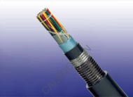
Foam Skin Insulated & AP Sheathed (ALPETH) Jelly Filled Cables to GR-421
Application
The GR-421 cables are designed for use in access or trunk networks, from telephone exchange to subscriber area. The cables are suitable for installation in ducts, direct burial in the ground and also for aerial installation with integral suspension strand.Jelly filled option is for subscriber’s cables installed underground or along the edge of pavement. An armoured option is offered for direct burial installations where additional mechanical or rodent protection is required. A figure-8 self support option is offered for aerial installation.
Standards
• Telcordia (Bellcore) GR-421
Construction


Conductors
Solid annealed bare copper, 0.4/0.5/0.63/0.9mm as per ASTM B-3/class 1 of IEC 60028
Insulation
Foam Skin which is a composite polyethylene insulation made of an inner cellular layer and an outer solid skin as per ASTM D 1248/IEC 60708
Twisted Pairs
Insulated conductors are twisted into pairs with varying lay length to minimize crosstalk
Cabling Element
Twisted Pairs
Cable Core Assembly
Cables with up to 400 pairs are composed of 25-pair units or 12/13-pair units; cables with over 400 pairs are composed of 50 or 100-pair units. Any extra pairs form a separate unit. Units are identified by colour coded binders. Standard construction is per GR-421 given in Cable Make Up Diagram
Core Wrapping(optional)
One or more non-hygroscopic polyester tapes are helically or longitudinally laid with an overlap. These tapes furnish thermal, mechanical as well as high dielectric protection between shielding and individual conductors
Moisture Barrier
A layer of bare aluminium tape (0.2mm/8mil) is applied longitudinally with overlap over the cable core to provide 100% electrical shielding coverage and ensures a barrier against water vapor. In cables with more than 200 pairs, the aluminum tape may be corrugated for improved cable flexibility
Filling
The cable core interstices are filled with petroleum jelly to avoid longitudinal water penetration within the cable.
The water resistant filling compound is applied to the air space between non-hygroscopic tape and shield, shield and sheath within the cable core
Sheath
Black low density polyethylene as per ASTM D 1248/IEC 60708, being able to withstand exposure to sunlight,
temperature variations, ground chemicals and other environmental contaminants
Ripcord(optional)
Ripcord may be provided for slitting the sheath longitudinally to facilitate its removal
Spare Pairs (optional)
Spare pairs may be incorporated for large pair cables
Continuity Wire (optional)
One tinned copper drain wire may be longitudinally laid to ensure electrical continuity of the screen
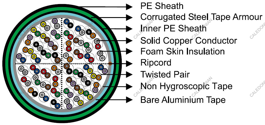
Optional Construction
Armoured Cable
Steel wire armour or corrugated steel tape armour applied over an optional inner polyethylene sheath.For steel tape version, the 0.15mm/6mil thick steel tape is coated with a copolymer and applied with an overlap. An outer polyethylene sheath is applied over the armour
Self-Support Cables
A 7-strand galvanized steel strand is used as support wire. Black polyethylene sheath covers both core and support wire in a figure-8 construction
Electrical Properties
| Nominal Conductor Diameter | mm | 0.4 | 0.5 | 0.63 | 0.9 |
|---|---|---|---|---|---|
| Conductor Gauge Size | AWG | 26 | 24 | 22 | 19 |
| Maximum Average DC Resistance | Ω/km / Ω/mile | 140/225 | 87/140 | 55/88.6 | 27.0/43.4 |
| Maximum Individual DC Resistance | Ω/km / Ω/mile | 144.2/232 | 89.5/144 | 56.5/91.0 | 28.0/45.0 |
| Minimum Insulation Resistance @500V DC | MΩ.km / MΩ.mile | 1600/1000 | 1600/1000 | 1600/1000 | 1600/1000 |
| Maximum Average Resistance Unbalance | % | 1.5 | 1.5 | 1.5 | 1.5 |
| Maximum Individual Resistance Unbalance | % | 5 | 5 | 5 | 5 |
| Average Mutual Capacitance | nF/km / nF/kft | 48.5-54.0 /14.8-16.5 | 48.5-54.0 /14.8-16.5 | 48.5-54.0 /14.8-16.5 | 48.5-54.0 /14.8-16.5 |
| Maximum Individual Mutual Capacitance | nF/km / nF/kft | 57/17.4 | 57/17.4 | 57/17.4 | 57/17.4 |
| Maximum Individual Capacitance Unbalance pair-to-pair | pF/km / pF/kft | 145/44 | 145/44 | 145/44 | 145/44 |
| Capacitance Unbalance RMS pair-to-pair | pF/km / pF/kft | 45/13.7 | 45/13.7 | 45/13.7 | 45/13.7 |
| Maximum Individual Capacitance Unbalance pair-to-ground | pF/km / pF/kft | 2625/800 | 2625/800 | 2625/800 | 2625/800 |
| Maximum Average Capacitance Unbalance pair-to-ground | pF/km / pF/kft | 574/175 | 574/175 | 574/175 | 574/175 |
| Maximum Conductor Loop Resistance @20°C | Ω/km / Ω/mile | 300/482 | 192/309 | 114/183.6 | 60/96.4 |
| Impedance @1KHz | Ω | 994 | 796 | 660 | 445 |
| Impedance @100KHz | Ω | 147 | 134 | 125 | 122 |
| Impedance @512KHz | Ω | 120 | 118 | 117 | 116 |
| Impedance @1MHz | Ω | 117 | 115 | 114 | 113 |
| Maximum Average Attenuation @0.8KHz | dB/km / dB/kft | 1.64/0.5 | 1.30/0.39 | 1.04/0.32 | 0.74/0.22 |
| Maximum Average Attenuation @1KHz | dB/km / dB/kft | 1.68/0.51 | 1.35/0.41 | 1.08/0.33 | 0.76/0.23 |
| Maximum Average Attenuation @3KHz | dB/km / dB/kft | 3.18/0.97 | 2.52/0.77 | 2.01/0.61 | 1.42/0.43 |
| Maximum Average Attenuation @150KHz | dB/km / dB/kft | 11.4/3.47 | 8.3/2.53 | 6.2/1.89 | 4.4/1.34 |
| Maximum Average Attenuation @772KHz | dB/km / dB/kft | 24.3/7.4 | 19.4/5.9 | 15.4/4.7 | 10.8/3.3 |
| Maximum Average Attenuation @1000KHz | dB/km / dB/kft | 27.1/8.25 | 21.4/6.52 | 17.5/5.33 | 12.8/3.89 |
| Dielectric Strength | |||||
| Conductor to Conductor (3secs) | V DC | 2400 | 3000 | 4000 | 5000 |
| Conductor to Screen (3secs) | V DC | 10000 | 10000 | 10000 | 10000 |
1 2

