


PRODUCTS
- Aerial Bundled Cables
- Airport Cables
- Automotive Cables
- Alarm & Audio & Electronic Cables
- Belden Equivalent Cables
- Bus Cables
- Cable Glands
- Cables for Oil Industry
- Coaxial Cables
- Composite Cables
- Control Cables
- Data Cable
- Elevator Cables
- Fiber Optic Cables
- Fire Resisting Cable(Fireflix)
- Fire Retardant Cable(FIRETOX)
- Flame Retardant Cable (FIREGUARD)
- Flexible Cables
- Heat Detection Cables
- High Temperature Cables
- Highway Cables
- Industrial Cables
- Instrumentation Cables
- Lan Cables
- Marine Cable
- NEK606 Water Blocked Offshore & Marine Cables
- IEC60092 STANDARD Offshore & Marine Cables
- BS 6883&BS7917 STANDARD Offshore & Marine Cables
- UKOOA Offshore & Marine cables
- VG 95218 Navy Cables
- Mining Cables
- Airframe Wire
- Marine, OIL,GAS & Petrochemical Cables
- Power Cables
- Railway Cables
- Robotics
- Rolling Stock Cables
- Rubber & Crane Cables
- Security Cables
- Special Cables
- Spiral Cables
- Telephone Cables
- Thermocouple Cables
- BS 5308 Cable
- PAS 5308 Cable
- BS 5467 Cable
- BS 6724 Cable
- BS 6346 Cable
- BS 7211 Cable
- IEC 60502-1 Cable
HOT PRODUCTS


APPLICATIONS
|
Cellular PE Insulated & LAP Sheathed Air Core/Jelly Filled Cables to DIN VDE 0816
Application
The DIN VDE 0816 telephone cables are designed for use as connection between central offices. The cables are suitable for installation in ducts, direct burial in the ground and also for aerial installation with integral suspension strand. Jelly filled option is for subscriber’s cables installed underground or along the edge of pavement. An armoured option is offered for direct burial installations. A figure-8 self support option is offered for aerial installation.
Standards
• DIN VDE 0816
Construction


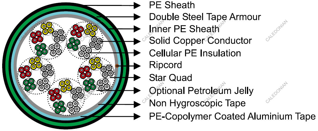
Conductors
Solid annealed bare copper 0.4/0.6/0.8mm, as per class 1 of DIN VDE 0295/ BS 6360/IEC 60228
Insulation
Cellular polyethylene 2YI2 type as per VDE 0207-2
Twisted Pairs
Insulated conductors are twisted into pairs with varying lay length to minimize crosstalk
Cabling Element
Star Quads
Cable Core Assembly
4 Cores are twisted into star quad. 5 star quads are stranded into a basic unit. 5 or 10 basic units each are stranded into one main unit. The star quads are grouped in units and stranded in layers to form the cable core.Standard make up is per VDE 0816 in the Cable Make Up Diagram
Core Wrapping
One or more non-hygroscopic polyester tapes are helically or longitudinally laid with an overlap. These tapes furnish thermal, mechanical as well as high dielectric protection between shielding and individual conductors
Moisture Barrier
A layer of aluminium tape (0.2mm) coated with PE-copolymer on one or both sides is applied longitudinally with overlap over the cable core to provide 100% electrical shielding coverage and ensures a barrier against water vapor
Sheath
Black low or medium density polyethylene 2YM2 type as per VDE 0207-3, being able to withstand exposure to
sunlight, temperature variations, ground chemicals and other environmental contaminants
Ripcord
Ripcord may be provided for slitting the sheath longitudinally to facilitate its removal
Spare Pairs (optional)
Spare pairs may be provided for large pair cables
Continuity Wire (optional)
Tinned copper drain wire may be longitudinally laid to ensure electrical continuity of the screen
Optional Construction
Jelly Filled Cable
The cable core interstices are filled with petroleum jelly to avoid longitudinal water penetration within the cable. The water resistant filling compound is applied to the air space between non-hygroscopic tape and shield,shield and sheath within the cable core
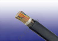
Armoured Cable
Corrugated steel tape armour is applied over an optional inner polyethylene sheath with an overlap. An outer polyethylene sheath is applied over the armour
Type Code
| A- | Outdoor Cable |
| 02Y | Cellular Polyethylene (FOAM PE) insulation |
| F | Continuous core filling |
| (L)2Y | Laminated sheath(copolymer-coated aluminium tape laminated to PE outer sheath) |
| SR | Corrugated steel tape |
| b | Armouring |
| T | Messenger of galvanized steel wires |
| StIII | Star quad in local cables |
| Bd | Unit-type stranding |
Electrical Properties
Mechanical and Thermal Properties
Temperature range during operation (fixed state): -30°C – +70°C
Temperature range during installation (mobile state): -20°C – +50°C
Minimum bending radius: 10 x Overall Diameter (unarmoured cables);15 x Overall Diameter (armoured cables)
Colour Code
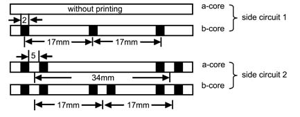
Quads
The single core is identified by black ring markings:
| Side Circuit 1 | a-wire | without marking |
| b-wire | 1 mark distance 17mm | |
| Side Circuit 2 | a-wire | 2 marks distance 34mm |
| b-wire | 2 marks distance 17mm |
Subunits
Basic colours for the wire insulation of the 5 star quads of a basic unit:
| Quad 1 Red | Quad 2 Green | |
| Quad 3 Grey | Quad 4 Yellow | Quad 5 White |
The tracer units are coded with a red helix, all other units by a white binder
Dimensions And Weigh
Cellular PE Insulated and LAP Sheathed Air Core Cable VDE CODE: A-02Y(L)2Y …x2x0.4/0.6/0.8 StIII Bd
1 2

