


PRODUCTS
- Aerial Bundled Cables
- Airport Cables
- Automotive Cables
- Alarm & Audio & Electronic Cables
- Belden Equivalent Cables
- Bus Cables
- Cable Glands
- Cables for Oil Industry
- Coaxial Cables
- Composite Cables
- Control Cables
- Data Cable
- Elevator Cables
- Fiber Optic Cables
- Fire Resisting Cable(Fireflix)
- Fire Retardant Cable(FIRETOX)
- Flame Retardant Cable (FIREGUARD)
- Flexible Cables
- Heat Detection Cables
- High Temperature Cables
- Highway Cables
- Industrial Cables
- Instrumentation Cables
- Lan Cables
- Marine Cable
- NEK606 Water Blocked Offshore & Marine Cables
- IEC60092 STANDARD Offshore & Marine Cables
- BS 6883&BS7917 STANDARD Offshore & Marine Cables
- UKOOA Offshore & Marine cables
- VG 95218 Navy Cables
- Mining Cables
- Airframe Wire
- Marine, OIL,GAS & Petrochemical Cables
- Power Cables
- Railway Cables
- Robotics
- Rolling Stock Cables
- Rubber & Crane Cables
- Security Cables
- Special Cables
- Spiral Cables
- Telephone Cables
- Thermocouple Cables
- BS 5308 Cable
- PAS 5308 Cable
- BS 5467 Cable
- BS 6724 Cable
- BS 6346 Cable
- BS 7211 Cable
- IEC 60502-1 Cable
HOT PRODUCTS


APPLICATIONS
|
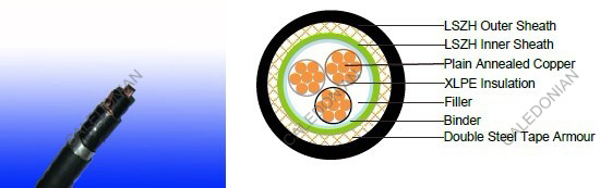
600/1000V XLPE Insulated, LSZH Sheathed, Double steel tape Armoured Power Cables (3cores)
FTX400 1RZ1MZ1-R (CU/XLPE/LSZH/DSTA/LSZH 600/1000V Class 2)
APPLICATION
The cables is mainly used in power stations, mass transit underground passenger systems, airports, petrochemical plants, hotels, hospitals, and high-rise buildings.STANDARDS
Basic design to IEC 60502-1FIRE PERFORMANCE
| Flame Retardance (Single Vertical Wire Test) | EN 60332-1-2; IEC 60332-1-2; BS EN 60332-1-2; VDE 0482-332-1 ; NBN C 30-004 (cat. F1); NF C32-070-2.1(C2); CEI 20-35/1-2; EN 50265-2-1*; DIN VDE 0482-265-2-1* |
| Reduced Fire Propagation (Vertically-mounted bundled wires & cable test) | EN 60332-3-24 (cat. C); IEC 60332-3-24; BS EN 60332-3-24; VDE 0482-332-3; NBN C 30-004 (cat. F2); NF C32-070-2.2(C1); CEI 20-22/3-4; EN 50266-2-4*; DIN VDE 0482-266-2-4 |
| Halogen Free | IEC 60754-1; EN 50267-2-1; DIN VDE 0482-267-2-1; CEI 20-37/2-1 ; BS 6425-1* |
| No Corrosive Gas Emission | IEC 60754-2; EN 50267-2-2; DIN VDE 0482-267-2-2; CEI 20-37/2-2 ; BS 6425-2* |
| minimum Smoke Emission | IEC 61034-1&2; EN 61034 -1&2; DIN VDE 0482-1034-1&2; CEI 20-37/3-1&2; EN 50268-1&2*; BS 7622-1&2* |
| No Toxic gases | NES 02-713; NF C 20-454 |
Note: Asterisk * denotes superseded standard.
VOLTAGE RATING
600/1000VCABLE CONSTRUCTION
Conductor: Plain annealed copper wire, normal stranded or compact stranded according to IEC(EN) 60228 class 2.Insulation: Extruded cross-linked XLPE compound.
Filler, binder and inner covering: PP, PET, LSZH
Armouring: Double steel tape
Outer Sheath: Thermoplastic LSZH compound type LTS3 as per BS 7655-6.1 (Thermosetting LSZH compound type SW2-SW4 as per BS 7655-2.6 can be offered.)
COLOUR CODE
Insulation Colour as per BS7671| with earth conductor | without earth conductor | |
| 2Cores | - | Brown,Blue |
| 3Cores | Yellow/Green,Brown,Blue | Brown,Gray,Black |
| 4Cores | Yellow/Green,Brown,Gray,Black | Brown,Gray,Black,Blue |
| 5Cores | Yellow/Green,Brown,Gray,Black,Blue | Brown,Gray,Black,Blue,Black |
| above 5 Cores | Yellow/Green,Black Numbered | Black Numbered |
Sheath Colour: Black
Physical AND THERMAL PROPERTIES
Temperature range during operation: Max.90°C for XLPE250°C in short-circuit for 5s max.
Minimum bending radius: 10x Overall Diameter
CONSTRUCTION PARAMETERS
| Conductor | FTX400 1RZ1MZ1-R | |||||||||
|---|---|---|---|---|---|---|---|---|---|---|
| No. of Core X Cross Section | Phases | Neutral | Nominal Diameter Overall Conducrtor | Nominal Insulation Thickness | Nominal Steel Tape Thickness | Nominal Sheath Thickness | Nominal Overall Diatemer | Approx. Weight | ||
| No./ Nominal Diameter of Strands | No./ Nominal Diameter of Strands | Pha. | Neu. | Pha. | Neu. | |||||
| mm2 | No/mm | No/mm | mm | mm | mm | mm | mm | mm | mm | Kg/km |
| 3xl0+lx6 | 7/Com | 7/Com | 3.75 | 2.90 | 0.7 | 0.7 | 0.2 | 1.8 | 20.1 | 740 |
| 3x16+1xl0 | 7/Com | 7/Com | 4.75 | 3.75 | 0.7 | 0.7 | 0.2 | 1.8 | 22.5 | 1,004 |
| 3x25+2x16 | 7/Com | 7/Com | 5.85 | 4.75 | 0.9 | 0.7 | 0.2 | 1.8 | 25.8 | 1,421 |
| 3x35+1x16 | 7/Com | 7/Com | 6.90 | 4.75 | 0.9 | 0.7 | 0.2 | 1.8 | 27.7 | 1,745 |
| 3x35+1x25 | 7/Com | 7/Com | 6.90 | 5.85 | 0.9 | 0.9 | 0.2 | 1.8 | 28.6 | 1,864 |
| 3x50+lx25 | 7/Com | 7/Com | 8.15 | 5.85 | 1.0 | 0.9 | 0.2 | 1.8 | 31.3 | 2,358 |
| 3x50+1x35 | 7/Com | 7/Com | 8.15 | 6.90 | 1.0 | 0.9 | 0.2 | 1.9 | 32.0 | 2.72 |
| 3x70+1x35 | 19/Com | 7/Com | 9.75 | 6.90 | I.1 | 0.9 | 0.2 | 2.0 | 35.9 | 3166 |
| 3x70+1x50 | 19/Com | 7/Com | 9.75 | 8.15 | I.1 | 1.0 | 0.2 | 2.0 | 36.8 | 3.341 |
| 3x95+lx50 | 19/Com | 7/Com | 11.4 | 8.15 | I.1 | 1.0 | 0.5 | 2.1 | 41.4 | 4,611 |
| 3x120+1x70 | 19/Com | 19/Com | 12.8 | 9.75 | 1.2 | I.1 | 0.5 | 2.3 | 45.6 | 5682 |
| 3x150+1x95 | 19/Com | 19/Com | 14.3 | 11.4 | 1.4 | I.1 | 0.5 | 2.4 | 50.8 | 7,072 |
| 3x150+1x120 | 19/Com | 19/Com | 14.3 | 12.8 | 1.4 | 1.2 | 0.5 | 2.5 | 51.8 | 7,357 |
| 3xI85+1x95 | 37/Com | 19/Com | 15.9 | 11.4 | 1.6 | I.1 | 0.5 | 2.6 | 54.7 | 8,348 |
| 3x185+1x120 | 37/Com | 19/Com | 15.9 | 12.8 | 1.6 | 1.2 | 0.5 | 2.6 | 55.8 | 8638 |
| 3x240+1x120 | 37/Com | 19/Com | 18.2 | 12.8 | 1.7 | 1.2 | 0.5 | 2.7 | 61.0 | 10,660 |
| 3x240+1x150 | 37/Com | 19/Com | 18.2 | 14.3 | 1.7 | 1.4 | 0.5 | 2.8 | 62.2 | 11024 |
| 3x300+1x150 | 37/Com | 19/Com | 20.4 | 14.3 | 1.8 | 1.4 | 0.5 | 2.9 | 66.8 | 12,809 |
| 3x300+1xI85 | 37/Com | 37/Com | 20.4 | 15.9 | 1.8 | 1.6 | 0.5 | 3.0 | 68.1 | 13,256 |
Notes:
1) *All conductors in accordance with lEC 60228. Compact shape (Com.) or non-compact depending on order.
2) Beside above list we can also provide others size depend on customer's requirement.
Electrical PROPERTIES
| No. of Core X Cross Section | Conductor | Max.DC resistance of conductor @20°C | ||||
|---|---|---|---|---|---|---|
| Phases | Neutral | Dia.Overall Conducrtor | ||||
| No./Nominal Diameter of Strands | No./Nominal Diameter of Strands | Pha. | Neu. | Pha. | Neu. | |
| mm2 | No/mm | No/mm | mm | mm | Ω/km | Ω/km |
| 3xl0+lx6 | 7/Com | 7/Com | 3.75 | 2.90 | 1.83 | 3.08 |
| 3x16+1xl0 | 7/Com | 7/Com | 4.75 | 3.75 | 1.15 | 1.83 |
| 3x25+2x16 | 7/Com | 7/Com | 5.85 | 4.75 | 0.727 | 1.15 |
| 3x35+1x16 | 7/Com | 7/Com | 6.90 | 4.75 | 0.524 | 1.15 |
| 3x35+1x25 | 7/Com | 7/Com | 6.90 | 5.85 | 0.524 | 0.727 |
| 3x50+lx25 | 7/Com | 7/Com | 8.15 | 5.85 | 0.387 | 0.727 |
| 3x50+1x35 | 7/Com | 7/Com | 8.15 | 6.90 | 0.387 | 0.524 |
| 3x70+1x35 | 19/Com | 7/Com | 9.75 | 6.90 | 0268 | 0.524 |
| 3x70+1x50 | 19/Com | 7/Com | 9.75 | 8.15 | 0268 | 0.387 |
| 3x95+lx50 | 19/Com | 7/Com | 11.4 | 8.15 | 0.193 | 0.387 |
| 3x120+1x70 | 19/Com | 19/Com | 12.8 | 9.75 | 0.153 | 0.268 |
| 3x150+1x95 | 19/Com | 19/Com | 14.3 | 11.4 | 0.124 | 0.193 |
| 3x150+1x120 | 19/Com | 19/Com | 14.3 | 12.8 | 0.124 | 0.153 |
| 3xI85+1x95 | 37/Com | 19/Com | 15.9 | 11.4 | 0.0991 | 0.193 |
| 3x185+1x120 | 37/Com | 19/Com | 15.9 | 12.8 | 0.0991 | 0.153 |
| 3x240+1x120 | 37/Com | 19/Com | 18.2 | 12.8 | 0.0754 | 0.153 |
| 3x240+1x150 | 37/Com | 19/Com | 18.2 | 14.3 | 0.0754 | 0.124 |
| 3x300+1x150 | 37/Com | 19/Com | 20.4 | 14.3 | 0.0601 | 0.124 |
| 3x300+1xI85 | 37/Com | 37/Com | 20.4 | 15.9 | 0.0601 | 0.0991 |
Electrical PROPERTIES
Conductor Operating Temperature : 90°C
Ambient Temperature : 30°C
Current-Carrying Capacities (Amp)
| Conductor crosssectional area | Reference Method 1 (clipped direct | Reference Method 11 (on a perforated horizontal cable trayor Reference Method 13 [free air] ) | In single-way ducts | Laid direct in ground | ||||
|---|---|---|---|---|---|---|---|---|
| one 2-core cable single phase a.c. or d.c. | one 3-core or 4-core cable 3-phase a.c. | one 2-core cable single phase a.c. or d.c. | one 3-core or 4-core cable 3-phase a.c. | one 2-core cable single phase a.c. or d.c. | one 3-core or 4-core cable 3-phase a.c. | one 2-core cable single phase a.c. or d.c. | one 3-core or 4-core cable 3-phase a.c. | |
| 1 | 2 | 3 | 4 | 5 | 6 | 7 | 8 | 9 |
| mm2 | A | A | A | A | A | A | A | A |
| 10 | 85 | 73 | 90 | 78 | - | 65 | - | 80 |
| 16 | 110 | 94 | 115 | 99 | 115 | 94 | 140 | 115 |
| 25 | 146 | 124 | 152 | 131 | 145 | 125 | 180 | 150 |
| 35 | 180 | 154 | 188 | 162 | 175 | 150 | 215 | 180 |
| 50 | 219 | 187 | 228 | 197 | 210 | 175 | 255 | 215 |
| 70 | 279 | 238 | 291 | 251 | 260 | 215 | 315 | 265 |
| 95 | 338 | 289 | 354 | 304 | 310 | 260 | 380 | 315 |
| 120 | 392 | 335 | 410 | 353 | 355 | 300 | 430 | 360 |
| 150 | 451 | 386 | 472 | 406 | 400 | 335 | 480 | 405 |
| 185 | 515 | 441 | 539 | 463 | 455 | 380 | 540 | 460 |
| 240 | 607 | 520 | 636 | 546 | 520 | 440 | 630 | 530 |
| 300 | 698 | 599 | 732 | 628 | 590 | 495 | 700 | 590 |
Voltage Drop (Per Amp Per Meter)
| Conductor cross-sectional area | 2-core cable d.c. | 2 cables, single-phase a.c. | 3 or 4 cables, 3-phase a.c. | 2 cables, single- phase a.c. | 3 or 4 cables, 3-phase a.c. | ||||
|---|---|---|---|---|---|---|---|---|---|
| In ducts or in ground | In ducts or in ground | ||||||||
| 1 | 2 | 3 | 4 | 5 | 6 | ||||
| mm2 | mV/A/m | mV/A/m | mV/A/m | mV/A/m | mV/A/m | ||||
| 6 | 7.9 | 7.9 | 6.8 | 7.9 | 6.5 | ||||
| 10 | 4.7 | 4.7 | 4.0 | 4.7 | 3.9 | ||||
| 16 | 2.9 | 2.9 | 2.5 | 2.9 | 2.6 | ||||
| r | x | z | r | x | z | ||||
| 25 | 1.850 | 1.350 | 0.160 | 1.900 | 1.600 | 0.140 | 1.650 | 1.900 | 1.600 |
| 35 | 1.350 | 1.350 | 0.155 | 1.350 | 1.150 | 0.135 | 1.150 | 1.350 | 1.200 |
| 50 | 0.980 | 0.990 | 0.155 | 1.000 | 0.860 | 0.135 | 0.870 | 1.000 | 0.870 |
| 70 | 0.670 | 0.670 | 0.150 | 0.690 | 0.590 | 0.130 | 0.600 | 0.690 | 0.610 |
| 95 | 0.490 | 0.500 | 0.150 | 0.520 | 0.430 | 0.130 | 0.450 | 0.520 | 0.450 |
| 120 | 0.390 | 0.400 | 0.145 | 0.420 | 0.340 | 0.130 | 0.370 | 0.420 | 0.360 |
| 150 | 0.310 | 0.320 | 0.145 | 0.350 | 0.280 | 0.125 | 0.300 | 0.350 | 0.300 |
| 185 | 0.250 | 0.260 | 0.145 | 0.290 | 0.220 | 0.125 | 0.260 | 0.290 | 0.250 |
| 240 | 0.195 | 0.200 | 0.140 | 0.240 | 0.175 | 0.125 | 0.210 | 0.240 | 0.210 |
| 300 | 0.155 | 0.160 | 0.140 | 0.210 | 0.140 | 0.120 | 0.185 | 0.210 | 0.190 |
| 400 | 0.120 | 0.130 | 0.140 | 0.190 | 0.115 | 0.120 | 0.165 | 0.190 | 0.180 |
© 2022 Caledonian cables

