


PRODUCTS
- Aerial Bundled Cables
- Airport Cables
- Automotive Cables
- Alarm & Audio & Electronic Cables
- Belden Equivalent Cables
- Bus Cables
- Cable Glands
- Cables for Oil Industry
- Coaxial Cables
- Composite Cables
- Control Cables
- Data Cable
- Elevator Cables
- Fiber Optic Cables
- Fire Resisting Cable(Fireflix)
- Fire Retardant Cable(FIRETOX)
- Flame Retardant Cable (FIREGUARD)
- Flexible Cables
- Heat Detection Cables
- High Temperature Cables
- Highway Cables
- Industrial Cables
- Instrumentation Cables
- Lan Cables
- Marine Cable
- NEK606 Water Blocked Offshore & Marine Cables
- IEC60092 STANDARD Offshore & Marine Cables
- BS 6883&BS7917 STANDARD Offshore & Marine Cables
- UKOOA Offshore & Marine cables
- VG 95218 Navy Cables
- Mining Cables
- Airframe Wire
- Marine, OIL,GAS & Petrochemical Cables
- Power Cables
- Railway Cables
- Robotics
- Rolling Stock Cables
- Rubber & Crane Cables
- Security Cables
- Special Cables
- Spiral Cables
- Telephone Cables
- Thermocouple Cables
- BS 5308 Cable
- PAS 5308 Cable
- BS 5467 Cable
- BS 6724 Cable
- BS 6346 Cable
- BS 7211 Cable
- IEC 60502-1 Cable
HOT PRODUCTS


APPLICATIONS
|
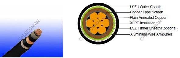
600/1000V XLPE Insulated, LSZH Sheathed, Armoured Power Cables (single core)
FTX300 1RCZ1MZ1-R (CU/XLPE/CUTO/LSZH/AWA/LSZH 600/1000V Class 2)
APPLICATION
This range of screened cables drastically reduce interferences from electrical noise, especially in Variable Speed Drive (VSD) applications and are manufactured with fixed conductors.STANDARDS
Basic design to IEC 60502-1FIRE PERFORMANCE
| Flame Retardance (Single Vertical Wire Test) | EN 60332-1-2; IEC 60332-1-2; BS EN 60332-1-2; VDE 0482-332-1 ; NBN C 30-004 (cat. F1); NF C32-070-2.1(C2); CEI 20-35/1-2; EN 50265-2-1*; DIN VDE 0482-265-2-1* |
| Reduced Fire Propagation (Vertically-mounted bundled wires & cable test) | EN 60332-3-24 (cat. C); IEC 60332-3-24; BS EN 60332-3-24; VDE 0482-332-3; NBN C 30-004 (cat. F2); NF C32-070-2.2(C1); CEI 20-22/3-4; EN 50266-2-4*; DIN VDE 0482-266-2-4 |
| Halogen Free | IEC 60754-1; EN 50267-2-1; DIN VDE 0482-267-2-1; CEI 20-37/2-1 ; BS 6425-1* |
| No Corrosive Gas Emission | IEC 60754-2; EN 50267-2-2; DIN VDE 0482-267-2-2; CEI 20-37/2-2 ; BS 6425-2* |
| minimum Smoke Emission | IEC 61034-1&2; EN 61034 -1&2; DIN VDE 0482-1034-1&2; CEI 20-37/3-1&2; EN 50268-1&2*; BS 7622-1&2* |
| No Toxic gases | NES 02-713; NF C 20-454 |
Note: Asterisk * denotes superseded standard.
VOLTAGE RATING
600/1000VCABLE CONSTRUCTION
Conductor: Plain annealed copper wire, stranded according to IEC(EN) 60228 class 2.Insulation: Extruded cross-linked XLPE compound.
Overall Screen: Copper Tape
Inner sheath: LSZH Compound
Armouring: Aluminium Wire
Outer Sheath: Thermoplastic LSZH compound type LTS3 as per BS 7655-6.1 (Thermosetting LSZH
compound type SW2-SW4 as per BS 7655-2.6 can be offered.)
COLOUR CODE
Insulation colour as per bs7671| with earth conductor | without earth conductor | |
| 2Cores | - | Brown,Blue |
| 3Cores | Yellow/Green,Brown,Blue | Brown,Gray,Black |
| 4Cores | Yellow/Green,Brown,Gray,Black | Brown,Gray,Black,Blue |
| 5Cores | Yellow/Green,Brown,Gray,Black,Blue | Brown,Gray,Black,Blue,Black |
| above 5 Cores | Yellow/Green,Black Numbered | Black Numbered |
sheath colour: Black
Physical AND THERMAL PROPERTIES
Maximum conductor temperature: Max 90°C for XLPEMinimum bending radius: 12 x Overall Diameter (for 70mm2 to 1000mm2)
CONSTRUCTION PARAMETERS
| Conductor | FTX300 1RCZ1MZ1-R | |||||||
|---|---|---|---|---|---|---|---|---|
| No. of Core X Cross Section | No./ Nominal Diameter of Strands | Nominal Insulation Thickness | Nominal Sheath Thickness | Diameter Under Screen | Diameter Over Inner Sheath | Armour Wire Diameter | Nominal Overall Diameter | Approx. Weight |
| mm2 | No./mm | mm | mm | kg/km | mm | mm | mm | kg/km |
| 1x70 | 19/2.14 | 1.1 | 1.8 | 15.2 | 17.6 | 20.1 | 23.9 | 1400 |
| 1x95 | 19/2.52 | 1.1 | 1.8 | 17.1 | 19.5 | 22.0 | 25.8 | 1700 |
| 1x120 | 37/2.03 | 1.2 | 1.8 | 19.0 | 20.8 | 24.0 | 27.8 | 2000 |
| 1x150 | 37/2.25 | 1.4 | 1.8 | 21.0 | 22.8 | 26.0 | 29.8 | 2400 |
| 1x185 | 37/2.52 | 1.6 | 1.8 | 23.2 | 25.0 | 28.2 | 32.0 | 2800 |
| 1x240 | 61/2.25 | 1.7 | 1.9 | 26.1 | 27.9 | 31.1 | 35.1 | 3500 |
| 1x300 | 61/2.52 | 1.8 | 2.0 | 28.7 | 30.5 | 33.7 | 37.9 | 4200 |
| 1x400 | 61/2.85 | 2.0 | 2.1 | 32.5 | 34.3 | 38.3 | 42.7 | 5400 |
| 1x500 | 61/3.20 | 2.2 | 2.2 | 36.0 | 37.8 | 41.8 | 46.4 | 6500 |
| 1x630 | 127/2.52 | 2.4 | 2.3 | 40.4 | 42.2 | 46.2 | 51.0 | 8200 |
| 1x800 | 127/2.85 | 2.6 | 2.5 | 45.5 | 47.3 | 52.3 | 57.5 | 10400 |
| 1x1000 | 127/3.20 | 2.8 | 2.7 | 50.4 | 52.2 | 57.2 | 62.4 | 13000 |
Electrical PROPERTIES
Conductor Operating Temperature : 90°CAmbient Temperature : 30°C
Current-Carrying Capacities (Amp)
| Conductor crosssectional area | Reference Method 1 (clipped direct) | Reference Method 11 (on a perforated horizontal cable tray or Reference Method 13 [free air] ) | Reference Method 12 (free air) | In single-way ducts | Laid direct in ground | ||||
|---|---|---|---|---|---|---|---|---|---|
| 2 cables, singlephase a.c. or d.c. | 3 or 4 cables, 3-phase a.c. | 2 cables, singlephase a.c. or d.c. | 3 or 4 cables, 3-phase a.c. | 3 cables 3-phase a.c. trefoil touching | 2 cables, singlephase a.c. or d.c. | 3 or 4 cables, 3-phase a.c. | 2 cables, singlephase a.c. or d.c. | 3 or 4 cables, 3-phase a.c. | |
| 1 | 2 | 3 | 4 | 5 | 6 | 7 | 8 | 9 | 10 |
| mm2 | A | A | A | A | A | A | A | A | A |
| 70 | 303 | 277 | 322 | 293 | 285 | 310 | 280 | 340 | 290 |
| 95 | 367 | 333 | 389 | 352 | 346 | 365 | 330 | 405 | 345 |
| 120 | 425 | 383 | 449 | 405 | 402 | 410 | 370 | 460 | 389 |
| 150 | 488 | 437 | 516 | 462 | 463 | 445 | 405 | 510 | 435 |
| 185 | 557 | 496 | 587 | 524 | 529 | 485 | 440 | 580 | 490 |
| 240 | 656 | 579 | 689 | 612 | 625 | 550 | 500 | 670 | 560 |
| 300 | 755 | 662 | 792 | 700 | 720 | 610 | 550 | 750 | 630 |
| 400 | 853 | 717 | 899 | 767 | 815 | 640 | 580 | 830 | 700 |
| 500 | 962 | 791 | 1016 | 851 | 918 | 690 | 620 | 910 | 770 |
| 630 | 1082 | 861 | 1146 | 935 | 1027 | 750 | 670 | 1000 | 840 |
| 800 | 1170 | 904 | 1246 | 987 | 1119 | 828 | 735 | 1117 | 931 |
| 1000 | 1261 | 961 | 1345 | 1055 | 1214 | 919 | 811 | 1254 | 1038 |
Voltage Drop (Per Amp Per Meter)
| Conductor crosssectional area | 2 cables d.c. | 2 cables singlephase a.c. | 3 or 4 cables three-phase a.c. | 2 cables singlephase a.c. | 3 or 4 cables, 3-phase a.c. touching | |||||||||
|---|---|---|---|---|---|---|---|---|---|---|---|---|---|---|
| Reference Method 1 & 11 (touching) | Reference Method 1, 11 & 12 (in trefoil touching) | Reference Method 1 & 11 (Flat touching) | In ducts | In ground | In ducts | In ground | ||||||||
| 1 | 2 | 3 | 4 | 5 | 6 | 7 | 8 | 9 | ||||||
| mm2 | mV/A/m | mV/A/m | mV/A/m | mV/A/m | mV/A/m | mV/A/m | mV/A/m | mV/A/m | ||||||
| r | x | z | r | x | z | r | x | z | ||||||
| 70 | 0.67 | 0.68 | 0.20 | 0.71 | 0.59 | 0.17 | 0.62 | 0.6 | 0.25 | 0.65 | 0.80 | 0.70 | 0.70 | 0.61 |
| 95 | 0.49 | 0.51 | 0.195 | 0.55 | 0.44 | 0.17 | 0.47 | 0.46 | 0.24 | 0.52 | 0.65 | 0.53 | 0.56 | 0.46 |
| 120 | 0.39 | 0.41 | 0.190 | 0.45 | 0.35 | 0.165 | 0.39 | 0.38 | 0.24 | 0.44 | 0.55 | 0.43 | 0.48 | 0.37 |
| 150 | 0.31 | 0.33 | 0.185 | 0.38 | 0.29 | 0.160 | 0.33 | 0.31 | 0.23 | 0.39 | 0.50 | 0.37 | 0.43 | 0.32 |
| 185 | 0.25 | 0.27 | 0.185 | 0.33 | 0.23 | 0.160 | 0.28 | 0.26 | 0.23 | 0.34 | 0.45 | 0.31 | 0.39 | 0.27 |
| 240 | 0.195 | 0.21 | 0.180 | 0.28 | 0.18 | 0.155 | 0.24 | 0.21 | 0.22 | 0.30 | 0.40 | 0.26 | 0.35 | 0.23 |
| 300 | 0.155 | 0.17 | 0.175 | 0.25 | 0.145 | 0.150 | 0.21 | 0.17 | 0.22 | 0.28 | 0.37 | 0.24 | 0.32 | 0.21 |
| 400 | 0.115 | 0.145 | 0.170 | 0.22 | 0.125 | 0.150 | 0.195 | 0.160 | 0.21 | 0.27 | 0.35 | 0.21 | 0.30 | 0.19 |
| 500 | 0.093 | 0.125 | 0.170 | 0.21 | 0.105 | 0.145 | 0.180 | 0.145 | 0.20 | 0.25 | 0.33 | 0.20 | 0.28 | 0.18 |
| 630 | 0.073 | 0.105 | 0.165 | 0.195 | 0.092 | 0.145 | 0.170 | 0.135 | 0.195 | 0.24 | 0.30 | 0.19 | 0.26 | 0.17 |
| 800 | 0.056 | 0.090 | 0.160 | 0.190 | 0.086 | 0.140 | 0.165 | 0.130 | 0.180 | 0.23 | 0.28 | 0.18 | 0.24 | 0.16 |
| 1000 | 0.045 | 0.092 | 0.155 | 0.180 | 0.080 | 0.135 | 0.155 | 0.125 | 0.170 | 0.21 | 0.26 | 0.17 | 0.22 | 0.15 |
© 2022 Caledonian cables

