


PRODUCTS
- Aerial Bundled Cables
- Airport Cables
- Automotive Cables
- Alarm & Audio & Electronic Cables
- Belden Equivalent Cables
- Bus Cables
- Cable Glands
- Cables for Oil Industry
- Coaxial Cables
- Composite Cables
- Control Cables
- Data Cables
- Elevator Cables
- Fiber Optic Cables
- Fire Resisting Cable(Fireflix)
- Fire Retardant Cable(FIRETOX)
- Flame Retardant Cable (FIREGUARD)
- Flexible Cables
- Heat Detection Cables
- High Temperature Cables
- Highway Cables
- Industrial Cables
- Instrumentation Cables
- Marine Cable
- NEK606 Water Blocked Offshore & Marine Cables
- IEC60092 STANDARD Offshore & Marine Cables
- BS 6883&BS7917 STANDARD Offshore & Marine Cables
- UKOOA Offshore & Marine cables
- VG 95218 Navy Cables
- Mining Cables
- Airframe Wire
- Marine, OIL,GAS & Petrochemical Cables
- Power Cables
- Railway Cables
- Robotics
- Rolling Stock Cables
- Rubber & Crane Cables
- Security Cables
- Special Cables
- Spiral Cables
- Telephone Cables
- Thermocouple Cables
- BS 5308 Cable
- PAS 5308 Cable
- BS 5467 Cable
- BS 6724 Cable
- BS 6346 Cable
- BS 7211 Cable
- IEC 60502-1 Cable
HOT PRODUCTS


APPLICATIONS
|
Fire Resistant Optic Fiber Cable
Fire resistant Multi Loose Tube Fiber Optic cables
APPLICATION
The Fire resistant multi loose tube non metallic Fiber Optic cables are designed for outside plant, which is prone to electrical interference. They are mainly installed inside buildings, tunnels,subways or closed areas in general, specially designed to guarantee the signal transmission even in case of fire. The cable can also be used for direct burial for armoured version
STANDARDS
Basic design to Telcordia GR-20 / RUS 7 CFR 1755.900 (REA PE-90) / ICEA S 87-640
FIRE PERFORMANCE
| Circuit Integrity | IEC 60331-25; BS 6387 CWZ; DIN VDE 0472-814(FE180); CEI 20-36/2-1; SS229-1; NBN C 30-004 (cat. F3); NF C32-070-2.3(CR1) |
|---|---|
| System circuit integrity | DIN 4102-12, E30 depending on lay system |
| Flame Retardance (Single Vertical Wire Test) | EN 60332-1-2; IEC 60332-1-2; BS EN 60332-1-2; VDE 0482-332-1 ; NBN C 30-004 (cat. F1); NF C32-070-2.1(C2); CEI 20-35/1-2; EN 50265-2-1*; DIN VDE 0482-265-2-1* |
| Reduced Fire Propagation (Vertically-mounted bundled wires & cable test) | EN 60332-3-24 (cat. C); IEC 60332-3-24; BS EN 60332-3-24; VDE 0482-332-3; NBN C 30-004 (cat. F2); NF C32-070-2.2(C1); CEI 20-22/3-4; EN 50266-2-4*; DIN VDE 0482-266-2-4 |
| Halogen Free | IEC 60754-1; EN 50267-2-1; DIN VDE 0482-267-2-1; CEI 20-37/2-1 ; BS 6425-1* |
| No Corrosive Gas Emission | IEC 60754-2; EN 50267-2-2; DIN VDE 0482-267-2-2; CEI 20-37/2-2 ; BS 6425-2* |
| Minimum Smoke Emission | IEC 61034-1&2; EN 61034 -1&2; DIN VDE 0482-1034-1&2; CEI 20-37/3-1&2; EN 50268-1&2*; BS 7622-1&2* |
| No Toxic gases | NES 02-713; NF C 20-454 |
Note: Asterisk * denotes superseded standard.
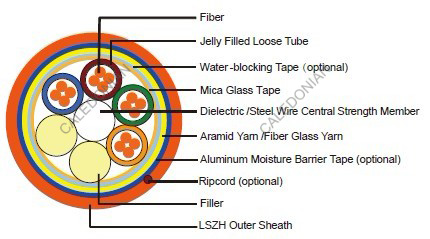
CABLE CONSTRUCTION
Fibers: Singlemode and multimode fibers, with loose tube technology.
Structure: The cable consists of 5 to 36 fibers containing tubes or fillers stranded in up to 3 layers
around a central strength member and bound under a LSZH sheath. Each tube contains 4 -12 fibers,
which is filled with water blocking gel.
Central Strength Member: Solid or stranded steel wire coated with polyethylene is usually used
as central strength member. Fiber glass reinforced plastics (FRP) will be used as central strength
member if non metallic construction is required.
Fire Barrier: The jelly filled tubes containing the fibers are individually wound with fire blocking mica
glass tape and are cabled around a central strength member
Water Blocking: The jelly filled tube is waterblocked by using swellable tape and thread.
Reinforcement: Either aramid yarn or fiber glass is wound around the tube to provide physical
protection and tensile strength, with added fire protection.
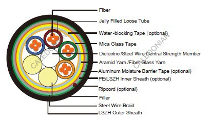
Inner Sheath (optional): The cable can be jacketed with either PE or Thermoplastic LSZH inner
sheath. PE is the preferred option in outdoor environment for water protection purpose.
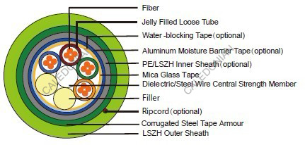
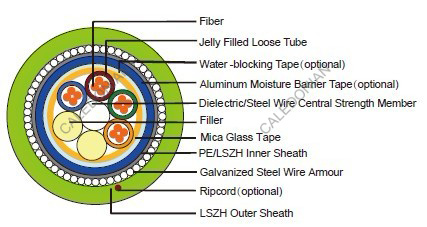
Armouring(optional): For diect burial, either galvanized steel wire braid, corrugated steel tape
armour or galvanized steel wire armour is applied over an inner polyethylene or LSZH sheath.
For steel tape armour, the 0.15mm thick steel tape is coated with a copolymer and applied with
an overlap. For steel wire braid or armour, single layer of galvanized steel wire braid or armour is
applied.
Moisture Barrier Tape (optional): An aluminum moisture tape can be incorporated under the
sheath for water blocking and shielding purpose.
Ripcord (optional): An optional ripcord can be located under the jacket to facilitate jacket removal.
Outer Sheath: Thermoplastic LSZH compound type LTS3 as per BS 7655-6.1(Thermosetting LSZH
compound type SW2-SW4 as per BS 7655-2.6 can be offered.)
Physical AND THERMAL PROPERTIES
Temperature range during operation (fixed state): -20°C - +60°C
Temperature range during installation (mobile state): 0°C - +50°C
Minimum Installation Bending Radius: 20 times the outer diameter
Minimum operation Bending Radius: 10 times the outer diameter for unarmoured cables
20 times the outer diameter for armoured cables
CONSTRUCTION
Unarmoured type
CONSTRUCTION PARAMETERS
| Cable Code | Fiber Count | Tube Diameter | Nominal Overall Diameter | Approx. Weight | Tension load | Crush |
|---|---|---|---|---|---|---|
| (n°) | mm | mm | kg/km | N | N/100mm | |
| MLA-B-C×D-F-H-J-FR | 72 | 2.5 | 15.0 | 230 | 4000 | 3000 |
| MLA-B-C×D-F-H-J-FR | 96 | 2.5 | 16.5 | 250 | 4000 | 3000 |
| MLA-B-C×D-F-H-J-FR | 144 | 2.5 | 20.5 | 280 | 4000 | 3000 |
Steel Wire Braid
| Cable Code | Fiber Count | Tube Diameter | Nominal Overall Diameter | Approx. Weight | Tension load | Crush |
|---|---|---|---|---|---|---|
| (n°) | mm | mm | kg/km | N | N/100mm | |
| MLA-B-C×D-F-2Y(SWB)H-J-FR | 72 | 2.5 | 15.0 | 280 | 3000 | 3500 |
| MLA-B-C×D-F-2Y(SWB)H-J-FR | 96 | 2.5 | 17.5 | 310 | 3000 | 3500 |
| MLA-B-C×D-F-2Y(SWB)H-J-FR | 144 | 2.5 | 21.5 | 350 | 3500 | 3500 |
Corrugated Steel Tape Armour
| Cable Code | Fiber Count | Tube Diameter | Nominal Overall Diameter | Approx. Weight | Tension load | Crush |
|---|---|---|---|---|---|---|
| (n°) | mm | mm | kg/km | N | N/100mm | |
| MLA-B-C×D-F-2Y(STA)H-J-FR | 72 | 2.5 | 16.5 | 290 | 3000 | 7500 |
| MLA-B-C×D-F-2Y(STA)H-J-FR | 96 | 2.5 | 18.5 | 350 | 3000 | 7500 |
| MLA-B-C×D-F-2Y(STA)H-J-FR | 144 | 2.5 | 22.5 | 450 | 3500 | 7500 |
Steel Wire armour
| Cable Code | Fiber Count | Tube Diameter | Nominal Overall Diameter | Approx. Weight | Tension load | Crush |
|---|---|---|---|---|---|---|
| (n°) | mm | mm | kg/km | N | N/100mm | |
| MLA-B-C×D-F-2Y(SWA)H-J-FR | 72 | 2.0 | 15.0 | 360 | 3500 | 5000 |
| MLA-B-C×D-F-2Y(SWA)H-J-FR | 96 | 2.0 | 16.5 | 390 | 4000 | 5000 |
| MLA-B-C×D-F-2Y(SWA)H-J-FR | 144 | 2.0 | 18.5 | 430 | 4500 | 5000 |
mechanical PROPERTIES
| Maximum Compressive Load: | 4000N for unarmoured cables 6000N for armoured cables |
|---|---|
| Repeated Impact: | 4.4 N.m (J) |
| Twist (Torsion): | 180×10 times, 125×OD |
| Cyclic Flexing: | 25 cycles for armoured cables 100 cycles for unarmoured cables |
| Crush Resistance: | 220N/cm(125lb/in) |
Fiber Compliance
| Temperature Cycling | IEC60794-1-2-F2 |
|---|---|
| Tensile Strength | IEC60794-1-2-E1A |
| Crush | IEC60794-1-2-E3 |
| Impact | IEC60794-1-2-E4 |
| Repeated Bending | IEC60794-1-2-E6 |
| Torsion | IEC60794-1-2-E7 |
| Kink | IEC60794-1-2-E10 |
| Cable Bend | IEC60794-1-2-E11 |
| Cool Bend | IEC60794-1-2-E11 |

