


PRODUCTS
- Aerial Bundled Cables
- Airport Cables
- Automotive Cables
- Alarm & Audio & Electronic Cables
- Belden Equivalent Cables
- Bus Cables
- Cable Glands
- Cables for Oil Industry
- Coaxial Cables
- Composite Cables
- Control Cables
- Data Cables
- Elevator Cables
- Fiber Optic Cables
- Fire Resisting Cable(Fireflix)
- Fire Retardant Cable(FIRETOX)
- Flame Retardant Cable (FIREGUARD)
- Flexible Cables
- Heat Detection Cables
- High Temperature Cables
- Highway Cables
- Industrial Cables
- Instrumentation Cables
- Marine Cable
- NEK606 Water Blocked Offshore & Marine Cables
- IEC60092 STANDARD Offshore & Marine Cables
- BS 6883&BS7917 STANDARD Offshore & Marine Cables
- UKOOA Offshore & Marine cables
- VG 95218 Navy Cables
- Mining Cables
- Airframe Wire
- Marine, OIL,GAS & Petrochemical Cables
- Power Cables
- Railway Cables
- Robotics
- Rolling Stock Cables
- Rubber & Crane Cables
- Security Cables
- Special Cables
- Spiral Cables
- Telephone Cables
- Thermocouple Cables
- BS 5308 Cable
- PAS 5308 Cable
- BS 5467 Cable
- BS 6724 Cable
- BS 6346 Cable
- BS 7211 Cable
- IEC 60502-1 Cable
HOT PRODUCTS


APPLICATIONS
|
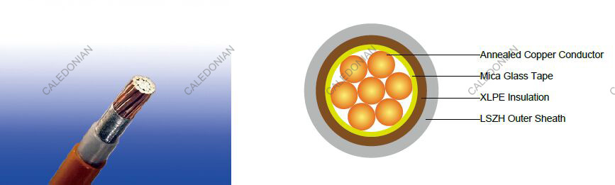
450/750V Mica+XLPE Insulated, LSZH Sheathed Fire Resistant Power Cables to BS 7211 (2-5 Cores)
FFX200 07mRZ1-U/R (CU/MGT+XLPE/LSZH 450/750V Class 1/2)
APPLICATION
The BS7211 Fire Resistant Power cables are mainly used in power stations, mass transit underground passenger systems, airports, petrochemical plants, hotels, hospitals and high-rise buildings.
STANDARDS
Basic design adapted from BS 7211:2012
FIRE PERFORMANCE
| Circuit Integrity | IEC 60331-21; BS 6387; BS 8491 |
|---|---|
| Flame Retardance (Single Vertical Wire or cable test) | IEC 60332-1-2; EN 60332-1-2 |
| Reduced Fire Propagation (Vertically-mounted bundled wires & cables test) | IEC 60332-3-24; EN 60332-3-24 |
| Halogen Free | IEC 60754-1; EN 50267-2-1 |
| No Corrosive Gas Emission | IEC 60754-2; EN 50267-2-2 |
| Minimum Smoke Emission | IEC 61034-2; EN 61034-2 |
VOLTAGE RATING
450/750V
CABLE CONSTRUCTION
Conductor: Annealed copper conductor, solid or stranded according to BS EN 60228 class 1 or class 2.
Fire Barrier: Mica glass tape.
Insulation: XLPE type GP 8 according to BS 7655-1.3. Crosslinked polyolefin material type EI 5 according to
EN 50363-5 can be offered as option.
Inner Covering Option: The optional inner covering, where used, shall consist of an extruded layer of
synthetic polymeric material. It shall surround the laid-up two, three, four or five cores, giving the assembly a
practically circular shape.
Outer Sheath: Extruded LSZH type LTS 4 according to BS 7655-6.1.
Outer Sheath Option: UV resistance, hydrocarbon resistance, oil resistance, anti-rodent and anti-termite
properties can be offered as option.
COLOUR CODE
Insulation Colour:
2-core: Brown and blue.
3-core: Brown, black and grey.
4-core: Blue, brown black and grey.
5-core: Green/yellow, blue, brown black and grey.
Sheath Colour: White; other colours can be offered upon request.
Physical AND THERMAL PROPERTIES
Maximum temperature range during operation: 90°C
Maximum short circuit temperature (5 Seconds): 250°C
Minimum bending radius
OD<8mm: 4 × Overall Diameter
8mm≤OD≤12mm: 5 × Overall Diameter
OD>12mm: 6 × Overall Diameter
CONSTRUCTION PARAMETERS
| Conductor | FFX200 07mRZ1-U/R | ||||||
|---|---|---|---|---|---|---|---|
| No. of Cores × Cross-sectional Area | Conductor Class | Nominal Insulation Thickness | Nominal Inner Covering Thickness | Nominal Sheath Thickness | Min. Overall Diameter | Max. Overall Diameter | Approx. Weight |
| No.×mm2 | mm | mm | mm | mm | mm | kg/km | |
| 2×1.0 | 1 | 0.7 | 0.4 | 1.2 | 9.1 | 11.5 | 102 |
| 2×1.5 | 1 | 0.7 | 0.4 | 1.2 | 9.6 | 12.1 | 129 |
| 2×2.5 | 1 | 0.7 | 0.4 | 1.2 | 10.4 | 13.0 | 174 |
| 2×4 | 1 | 0.7 | 0.4 | 1.2 | 11.2 | 14.1 | 221 |
| 2×6 | 1 | 0.7 | 0.4 | 1.2 | 12.2 | 15.2 | 281 |
| 2×10 | 1 | 0.7 | 0.4 | 1.4 | 14.1 | 18.0 | 458 |
| 2×1.0 | 2 | 0.7 | 0.4 | 1.2 | 9.3 | 11.7 | 122 |
| 2×1.5 | 2 | 0.7 | 0.4 | 1.2 | 9.8 | 12.3 | 146 |
| 2×2.5 | 2 | 0.7 | 0.4 | 1.2 | 10.5 | 13.3 | 192 |
| 2×4 | 2 | 0.7 | 0.4 | 1.2 | 11.5 | 14.4 | 248 |
| 2×6 | 2 | 0.7 | 0.4 | 1.2 | 12.6 | 15.7 | 318 |
| 2×10 | 2 | 0.7 | 0.6 | 1.4 | 14.7 | 18.7 | 508 |
| 2×16 | 2 | 0.7 | 0.6 | 1.4 | 16.4 | 20.8 | 692 |
| 2×25 | 2 | 0.9 | 0.8 | 1.4 | 19.7 | 25.2 | 1063 |
| 2×35 | 2 | 0.9 | 0.8 | 1.6 | 22.0 | 28.0 | 1155 |
| 3×1.0 | 1 | 0.7 | 0.4 | 1.2 | 9.7 | 12.2 | 122 |
| 3×1.5 | 1 | 0.7 | 0.4 | 1.2 | 10.2 | 12.8 | 155 |
| 3×2.5 | 1 | 0.7 | 0.4 | 1.2 | 11.0 | 13.8 | 212 |
| 3×4 | 1 | 0.7 | 0.4 | 1.2 | 12.0 | 14.9 | 274 |
| 3×6 | 1 | 0.7 | 0.4 | 1.2 | 13.4 | 16.6 | 401 |
| 3×10 | 1 | 0.7 | 0.6 | 1.4 | 15.0 | 19.1 | 574 |
| 3×1.0 | 2 | 0.7 | 0.4 | 1.2 | 9.9 | 12.4 | 140 |
| 3×1.5 | 2 | 0.7 | 0.4 | 1.2 | 10.4 | 13.1 | 168 |
| 3×2.5 | 2 | 0.7 | 0.4 | 1.2 | 11.2 | 14.1 | 227 |
| 3×4 | 2 | 0.7 | 0.4 | 1.2 | 12.3 | 15.3 | 296 |
| 3×6 | 2 | 0.7 | 0.4 | 1.4 | 13.8 | 17.2 | 401 |
| 3×10 | 2 | 0.7 | 0.6 | 1.4 | 15.7 | 19.9 | 624 |
| 3×16 | 2 | 0.7 | 0.6 | 1.4 | 17.5 | 22.1 | 867 |
| 3×25 | 2 | 0.9 | 0.8 | 1.4 | 21.1 | 26.8 | 1338 |
| 3×35 | 2 | 0.9 | 0.8 | 1.6 | 23.5 | 29.8 | 1585 |
| 4×1.0 | 1 | 0.7 | 0.4 | 1.2 | 10.5 | 13.1 | 146 |
| 4×1.5 | 1 | 0.7 | 0.4 | 1.2 | 11.1 | 13.8 | 186 |
| 4×2.5 | 1 | 0.7 | 0.4 | 1.2 | 12.0 | 15.0 | 258 |
| 4×4 | 1 | 0.7 | 0.4 | 1.2 | 13.1 | 16.2 | 348 |
| 4×6 | 1 | 0.7 | 0.4 | 1.4 | 14.6 | 18.5 | 463 |
| 4×10 | 1 | 0.7 | 0.6 | 1.4 | 16.5 | 20.8 | 710 |
| 4×1.0 | 2 | 0.7 | 0.4 | 1.2 | 10.7 | 13.4 | 166 |
| 4×1.5 | 2 | 0.7 | 0.4 | 1.2 | 11.3 | 14.1 | 201 |
| 4×2.5 | 2 | 0.7 | 0.4 | 1.2 | 12.3 | 15.2 | 274 |
| 4×4 | 2 | 0.7 | 0.4 | 1.2 | 13.4 | 16.6 | 362 |
| 4×6 | 2 | 0.7 | 0.6 | 1.4 | 15.1 | 19.1 | 508 |
| 4×10 | 2 | 0.7 | 0.6 | 1.4 | 17.2 | 21.6 | 770 |
| 4×16 | 2 | 0.7 | 0.6 | 1.4 | 19.3 | 24.2 | 1078 |
| 4×25 | 2 | 0.9 | 0.8 | 1.6 | 23.6 | 29.9 | 1602 |
| 4×35 | 2 | 0.9 | 1.0 | 1.6 | 25.9 | 33.1 | 2076 |
| 5×1.0 | 1 | 0.7 | 0.4 | 1.2 | 11.5 | 14.2 | 177 |
| 5×1.5 | 1 | 0.7 | 0.4 | 1.2 | 12.1 | 15.0 | 228 |
| 5×2.5 | 1 | 0.7 | 0.4 | 1.2 | 13.2 | 16.3 | 318 |
| 5×4 | 1 | 0.7 | 0.4 | 1.4 | 14.7 | 18.6 | 445 |
| 5×6 | 1 | 0.7 | 0.6 | 1.4 | 16.0 | 20.2 | 574 |
| 5×10 | 1 | 0.7 | 0.6 | 1.4 | 18.1 | 22.7 | 887 |
| 5×1.0 | 2 | 0.7 | 0.4 | 1.2 | 11.7 | 14.6 | 203 |
| 5×1.5 | 2 | 0.7 | 0.4 | 1.2 | 12.4 | 15.3 | 247 |
| 5×2.5 | 2 | 0.7 | 0.4 | 1.2 | 13.4 | 16.6 | 340 |
| 5×4 | 2 | 0.7 | 0.6 | 1.4 | 15.1 | 19.1 | 483 |
| 5×6 | 2 | 0.7 | 0.6 | 1.4 | 16.5 | 20.8 | 633 |
| 5×10 | 2 | 0.7 | 0.6 | 1.4 | 18.9 | 23.6 | 968 |
| 5×16 | 2 | 0.7 | 0.8 | 1.4 | 21.2 | 26.9 | 1,359 |
| 5×25 | 2 | 0.9 | 1.0 | 1.6 | 26.0 | 33.2 | 1,899 |
| 5×35 | 2 | 0.9 | 1.0 | 1.6 | 28.6 | 36.3 | 2,539 |
Electrical PROPERTIES
Conductor operating temperature: 90°C
Ambient temperature: 30°C
Current-Carrying Capacities (Amp) according to BS 7671:2008 table 4E2A
| Conductor cross sectional area | Ref. Method A (enclosed in conduit in thermally insulating wall etc.) | Ref. Method B (enclosed in conduit on a wall or in trunking etc.) | Ref. Method C (clipped direct) | Ref. Method E (in free air or on a perforated cable tray etc. horizontal or vertical) | ||||
|---|---|---|---|---|---|---|---|---|
| 1 two-core cable*, single-phase a.c. or d.c. | 1 three- or four-core cable*, threephase a.c. | 1 two-core cable*, singlephase a.c. or d.c. | 1 three- or four-core cable*, three-phase a.c. | 1 two-core cable*, single-phase a.c. or d.c. | 1 three- or four-core cable*, threephase a.c. | 1 two-core cable*, singlephase a.c. or d.c. | 1 three- or four-core cable*, threephase a.c. | |
| 1 | 2 | 3 | 4 | 5 | 6 | 7 | 8 | 9 |
| mm2 | a | a | a | a | a | a | a | a |
| 1.0 | 14.5 | 13 | 17 | 15 | 19 | 17 | 21 | 18 |
| 1.5 | 18.5 | 16.5 | 22 | 19.5 | 24 | 22 | 26 | 23 |
| 2.5 | 25 | 22 | 30 | 26 | 33 | 30 | 36 | 32 |
| 4 | 33 | 30 | 40 | 35 | 45 | 40 | 49 | 42 |
| 6 | 42 | 38 | 51 | 44 | 58 | 52 | 63 | 54 |
| 10 | 57 | 51 | 69 | 60 | 80 | 71 | 86 | 75 |
| 16 | 76 | 68 | 91 | 80 | 107 | 96 | 115 | 100 |
| 25 | 99 | 89 | 119 | 105 | 138 | 119 | 149 | 127 |
| 35 | 121 | 109 | 146 | 128 | 171 | 147 | 185 | 158 |
Voltage Drop (Per Amp Per Meter) according to BS 7671:2008 table 4E2B
| Conductor crosssectional area | Two-core cable, d.c. | Two-core cable, single-phase a.c. | Three- or four-core cable, three-phase a.c. | ||||
|---|---|---|---|---|---|---|---|
| 1 | 2 | 3 | 4 | ||||
| mm2 | mV/a/m | mV/a/m | mV/a/m | ||||
| 1.0 | 46 | 46 | 40 | ||||
| 1.5 | 31 | 31 | 27 | ||||
| 2.5 | 19 | 19 | 16 | ||||
| 4 | 12 | 12 | 10 | ||||
| 6 | 7.9 | 7.9 | 6.8 | ||||
| 10 | 4.7 | 4.7 | 4.0 | ||||
| 16 | 2.9 | 2.9 | 2.5 | ||||
| r | x | z | r | x | z | ||
| 25 | 1.85 | 1.85 | 0.160 | 1.90 | 1.60 | 0.140 | 1.65 |
| 35 | 1.35 | 1.35 | 0.155 | 1.35 | 1.15 | 0.135 | 1.15 |

