


PRODUCTS
- Aerial Bundled Cables
- Airport Cables
- Automotive Cables
- Alarm & Audio & Electronic Cables
- Belden Equivalent Cables
- Bus Cables
- Cable Glands
- Cables for Oil Industry
- Coaxial Cables
- Composite Cables
- Control Cables
- Data Cables
- Elevator Cables
- Fiber Optic Cables
- Fire Resisting Cable(Fireflix)
- Fire Retardant Cable(FIRETOX)
- Flame Retardant Cable (FIREGUARD)
- Flexible Cables
- Heat Detection Cables
- High Temperature Cables
- Highway Cables
- Industrial Cables
- Instrumentation Cables
- Marine Cable
- NEK606 Water Blocked Offshore & Marine Cables
- IEC60092 STANDARD Offshore & Marine Cables
- BS 6883&BS7917 STANDARD Offshore & Marine Cables
- UKOOA Offshore & Marine cables
- VG 95218 Navy Cables
- Mining Cables
- Airframe Wire
- Marine, OIL,GAS & Petrochemical Cables
- Power Cables
- Railway Cables
- Robotics
- Rolling Stock Cables
- Rubber & Crane Cables
- Security Cables
- Special Cables
- Spiral Cables
- Telephone Cables
- Thermocouple Cables
- BS 5308 Cable
- PAS 5308 Cable
- BS 5467 Cable
- BS 6724 Cable
- BS 6346 Cable
- BS 7211 Cable
- IEC 60502-1 Cable
HOT PRODUCTS


APPLICATIONS
|
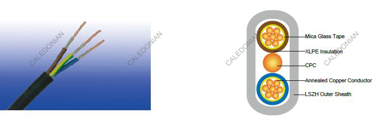
300/500V Mica+XLPE Insulated, LSZH Sheathed Fire Resistant Power Cables to BS 7211 (2-3 Cores)
FFX200 05mRZ1-U/R (CU/MGT+XLPE/LSZH 300/500V Class 1/2)
APPLICATION
The BS7211 Fire Resistant Power cables are mainly used in power stations, mass transit underground passenger systems, airports, petrochemical plants, hotels, hospitals and high-rise buildings.
STANDARDS
Basic design adapted from BS 7211:2012
FIRE PERFORMANCE
| Circuit Integrity | IEC 60331-21; BS 6387 |
|---|---|
| Flame Retardance (Single Vertical Wire or cable test) | IEC 60332-1-2; EN 60332-1-2 |
| Reduced Fire Propagation (Vertically-mounted bundled wires & cables test) | IEC 60332-3-24; EN 60332-3-24 |
| Halogen Free | IEC 60754-1; EN 50267-2-1 |
| No Corrosive Gas Emission | IEC 60754-2; EN 50267-2-2 |
| Minimum Smoke Emission | IEC 61034-2; EN 61034-2 |
VOLTAGE RATING
300/500V
CABLE CONSTRUCTION
Conductor: Annealed copper conductor, solid or stranded according to BS EN 60228 class 1 or class 2.
Fire Barrier: Mica glass tape.
Insulation: XLPE type GP 8 according to BS 7655-1.3. Crosslinked polyolefin material type EI 5 according to
EN 50363-5 can be offered as option.
CPC (Circuit Protective Conductor): Uninsulated copper conductor.
Outer Sheath: Extruded LSZH type LTS 2 according to BS 7655-6.1.
Outer Sheath Option: UV resistance, hydrocarbon resistance, oil resistance, anti-rodent and anti-termite
properties can be offered as option.
COLOUR CODE
Insulation Colour:
Twin: Brown and blue or, for 2x1.0 and 2x1.5 cables, brown and brown.
Three cores: Brown, black (centre core) and grey.
Position of CPC:
Twin: Centrally placed between cores in same plane.
Three cores: Centrally placed between black and grey cores in same plane.
Sheath Colour: White; other colours can be offered upon request.
Physical AND THERMAL PROPERTIES
Maximum temperature range during operation: 90°C
Maximum short circuit temperature (5 Seconds): 250°C
Minimum bending radius
OD<8mm: 4 × Overall Diameter
8mm≤OD≤12mm: 5 × Overall Diameter
OD>12mm: 6 × Overall Diameter
CONSTRUCTION PARAMETERS
| Conductor | FFX200 05mRZ1-U/R | |||||||
|---|---|---|---|---|---|---|---|---|
| No. of Cores × Cross-sectional Area | Conductor Class | Nominal Insulation Thickness | Crosssectional Area of CPC | Class of CPC | Nominal Sheath Thickness | Min. Overall Dimensions | Max. Overall Dimensions | Approx. Weight |
| No.×mm2 | mm | mm2 | mm | mm | mm | kg/km | ||
| 2×1.0 | 1 | 0.7 | 1.0 | 1 | 0.9 | 5.1×9.6 | 6.0×11.2 | 84 |
| 2×1.5 | 1 | 0.7 | 1.0 | 1 | 0.9 | 5.4×10.1 | 6.3×11.7 | 101 |
| 2×2.5 | 1 | 0.7 | 1.5 | 1 | 1.0 | 5.9×11.3 | 7.0×12.2 | 136 |
| 3×1.0 | 1 | 0.7 | 1.0 | 1 | 0.9 | 5.1×13.0 | 6.0×15.1 | 108 |
| 3×1.5 | 1 | 0.7 | 1.0 | 1 | 0.9 | 5.4×13.7 | 6.3×15.9 | 135 |
| 3×2.5 | 1 | 0.7 | 1.5 | 1 | 1.0 | 5.9×15.0 | 7.0×17.6 | 190 |
| 2×1.0 | 2 | 0.7 | 1.0 | 1 | 0.9 | 5.2×9.8 | 6.1×11.4 | 89 |
| 2×1.5 | 2 | 0.7 | 1.0 | 1 | 0.9 | 5.5×10.3 | 6.4×12.0 | 107 |
| 2×2.5 | 2 | 0.7 | 1.5 | 1 | 1.0 | 6.0×11.5 | 7.1×13.4 | 141 |
| 2×4 | 2 | 0.7 | 1.5 | 1 | 1.0 | 6.5×12.4 | 7.7×14.6 | 181 |
| 2×6 | 2 | 0.7 | 2.5 | 1 | 1.1 | 7.2×14.0 | 8.5×16.6 | 256 |
| 2×10 | 2 | 0.7 | 4.0 | 2 | 1.2 | 8.3×16.5 | 9.8×19.5 | 406 |
| 2×16 | 2 | 0.7 | 6.0 | 2 | 1.3 | 9.4×19.0 | 11.1×22.5 | 576 |
| 3×4 | 2 | 0.7 | 1.5 | 1 | 1.0 | 6.5×17.0 | 7.7×19.9 | 216 |
| 3×6 | 2 | 0.7 | 2.5 | 1 | 1.1 | 7.2×19.2 | 7.5×22.5 | 311 |
| 3×10 | 2 | 0.7 | 4.0 | 2 | 1.2 | 8.3×22.5 | 9.8×26.6 | 460 |
| 3×16 | 2 | 0.7 | 6.0 | 2 | 1.3 | 9.4×25.8 | 11.1×30.6 | 690 |
Electrical PROPERTIES
Conductor operating temperature: 90°C
Ambient temperature: 30°C
Current-Carrying Capacities (Amp) according to BS 7671:2008 table 4E2A
| Conductor crosssectional area | Ref. Method A (enclosed in conduit in thermally insulating wall etc.) | Ref. Method B (enclosed in conduit on a wall or in trunking etc.) | Ref. Method C (clipped direct) | Ref. Method E (free air or on a perforated cable tray etc. horizontal or vertical) | ||||
|---|---|---|---|---|---|---|---|---|
| 1 two-core cable*, single-phase a.c. or d.c. | 1 three-or four core cable*, threephase a.c. | 1 two-core cable*, singlephase a.c. or d.c. | 1 three-or four core cable*, three-phase a.c. | 1 two-core cable*, single-phase a.c. or d.c. | 1 three-or four core cable*, threephase a.c. | 1 two-core cable*, singlephase a.c. or d.c. | 1 three-or four core cable*, threephase a.c. | |
| 1 | 2 | 3 | 4 | 5 | 6 | 7 | 8 | 9 |
| mm2 | a | a | a | a | a | a | a | a |
| 1.0 | 14.5 | 13 | 17 | 15 | 19 | 17 | 21 | 18 |
| 1.5 | 18.5 | 16.5 | 22 | 19.5 | 24 | 22 | 26 | 23 |
| 2.5 | 25 | 22 | 30 | 26 | 33 | 30 | 36 | 32 |
| 4 | 33 | 30 | 40 | 35 | 45 | 40 | 49 | 42 |
| 6 | 42 | 38 | 51 | 44 | 58 | 52 | 63 | 54 |
| 10 | 57 | 51 | 69 | 60 | 80 | 71 | 86 | 75 |
| 16 | 76 | 68 | 91 | 80 | 107 | 96 | 115 | 100 |
Note: *With or without a protective conductor.
Voltage Drop (Per Amp Per Meter) according to BS 7671:2008 table 4E2B
| Conductor crosssectional area | Two-core cable, d.c. | Two-core cable, single-phase a.c. | Three- or four-core cable, three-phase a.c. |
|---|---|---|---|
| 1 | 2 | 3 | 4 |
| mm2 | mV/a/m | mV/a/m | mV/a/m |
| 1.0 | 46 | 46 | 40 |
| 1.5 | 31 | 31 | 27 |
| 2.5 | 19 | 19 | 16 |
| 4 | 12 | 12 | 10 |
| 6 | 7.9 | 7.9 | 6.8 |
| 10 | 4.7 | 4.7 | 4.0 |
| 16 | 2.9 | 2.9 | 2.5 |

