


PRODUCTS
- Aerial Bundled Cables
- Airport Cables
- Automotive Cables
- Alarm & Audio & Electronic Cables
- Belden Equivalent Cables
- Bus Cables
- Cable Glands
- Cables for Oil Industry
- Coaxial Cables
- Composite Cables
- Control Cables
- Data Cables
- Elevator Cables
- Fiber Optic Cables
- Fire Resisting Cable(Fireflix)
- Fire Retardant Cable(FIRETOX)
- Flame Retardant Cable (FIREGUARD)
- Flexible Cables
- Heat Detection Cables
- High Temperature Cables
- Highway Cables
- Industrial Cables
- Instrumentation Cables
- Marine Cable
- NEK606 Water Blocked Offshore & Marine Cables
- IEC60092 STANDARD Offshore & Marine Cables
- BS 6883&BS7917 STANDARD Offshore & Marine Cables
- UKOOA Offshore & Marine cables
- VG 95218 Navy Cables
- Mining Cables
- Airframe Wire
- Marine, OIL,GAS & Petrochemical Cables
- Power Cables
- Railway Cables
- Robotics
- Rolling Stock Cables
- Rubber & Crane Cables
- Security Cables
- Special Cables
- Spiral Cables
- Telephone Cables
- Thermocouple Cables
- BS 5308 Cable
- PAS 5308 Cable
- BS 5467 Cable
- BS 6724 Cable
- BS 6346 Cable
- BS 7211 Cable
- IEC 60502-1 Cable
HOT PRODUCTS


APPLICATIONS
|
Fire Resistant Power & Control Cable
600/1000V SR Insulated Flexibles Control Cables (2-4 Cores & Multicores)
FFX400 1SZ1-R(PH60)(CU/SR/LSZH 600/1000V Class 2)
FFX400 1SZ1-F(PH60)(CU/SR/LSZH 600/1000V Class 5)
APPLICATION
The 600/1000V SR Insulated Flexibles Fire Resistant Control Cables are designed for power supply and signals trasmission, indoor or outdoor even wet environment. They are designed for fixed laying in free air, in pipe or conduit, on masonry and metal structures or suspended in places where in case of fire people are exposed to serious risks for emission of smoke, toxic and corrosive gases and where you want to avoid damage to facilities, equipment, goods. They are primarily intended for feeding of: emergency exits, alarm signals, warning of smoke or gas, escalators.STANDARDS
Basic design adapted from BS 7629-1FIRE PERFORMANCE
| Circuit Integrity | IEC 60331-21; BS 6387 CWZ; DIN VDE 0472-814(FE180); BS 8434-1 (30mins); BS 5839-1 Clause 26 2d; CEI 20-36/2-1; SS229-1; NBN C 30-004 (cat. F3); NF C32-070-2.3(CR1) |
|---|---|
| Circuit Integrity with mechanical shock | EN 50200(PH60); CEI 20-36/4-0 |
| Circuit Integrity with mechanical shock & water spray | EN 50200 annex E |
| System circuit integrity | DIN 4102-12, E30 depending on lay system |
| Flame Retardance (Single Vertical Wire Test) | EN 60332-1-2; IEC 60332-1-2; BS EN 60332-1-2; VDE 0482-332-1 ; NBN C 30-004 (cat. F1); NF C32-070-2.1(C2); CEI 20-35/1-2; EN 50265-2-1*; DIN VDE 0482-265-2-1* |
| Reduced Fire Propagation (Vertically-mounted bundled wires & cable test) | EN 60332-3-24 (cat. C); IEC 60332-3-24; BS EN 60332-3-24; VDE 0482-332-3; NBN C 30-004 (cat. F2); NF C32-070-2.2(C1); CEI 20-22/3-4; EN 50266-2-4*; DIN VDE 0482-266-2-4 |
| Halogen Free | IEC 60754-1; EN 50267-2-1; DIN VDE 0482-267-2-1; CEI 20-37/2-1 ; BS 6425-1* |
| No Corrosive Gas Emission | IEC 60754-2; EN 50267-2-2; DIN VDE 0482-267-2-2; CEI 20-37/2-2 ; BS 6425-2* |
| Minimum Smoke Emission | IEC 61034-1&2; EN 61034 -1&2; DIN VDE 0482-1034-1&2; CEI 20-37/3-1&2; EN 50268-1&2*; BS 7622-1&2* |
| No Toxic gases | NES 02-713; NF C 20-454 |
Note: Asterisk * denotes superseded standard.
VOLTAGE RATING
600/1000 VCABLE CONSTRUCTION
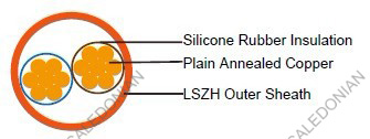
Conductors:Plain annealed copper wire, stranded for section up to 10mm2 according to IEC(EN) 60228 class 2 or flexible for section above 10mm2 according to IEC(EN) 60228 class 5.Insulation: Fire resistant silicone rubber compound type EI2 as per BS 7655-1.1.
Cabling: The cores are cabled together in concentric layers with suitable non-hygroscopic fillers.
Outer Sheath: Thermoplastic LSZH compound type LTS3 as per BS 7655-6.1 (Thermosetting LSZH compound type SW2-SW4 as per BS 7655-2.6 can be offered.)
COLOUR CODE
Insulation Colour:Without earth conductor
2 cores blue - brown
3 cores brown - black - grey
4 cores blue - brown - black - grey
5 cores blue - brown - black - grey - black With earth conductor
3 cores yellow/green - blue - brown
4 cores yellow/green - brown - black - grey
5 cores yellow/green - blue - brown - black - grey
Sheath Colour: red (other colours on request).
Physical AND THERMAL PROPERTIES
Temperature range during operation (fixed state): -30°C – +90°CTemperature range during installation (mobile state): -20°C – +50°C
Minimum bending radius: 6 x Overall Diameter
Electrical PROPERTIES
| Dielectric test: | 3500 V r.m.s. x 5' (core/core) |
|---|---|
| Insulation resistance | ≥300 MΩ x km (at 20°C) |
| Short circuit temperature | 350°C |
CONSTRUCTION PARAMETERS
| Cable Code | No. of Core X Cross Section | Nominal Insulation Thickness | Nominal Sheath Thickness | Nominal Overall Diameter | Approx. Weight |
|---|---|---|---|---|---|
| mm2 | mm | mm | mm | kg/km | |
| 2 core | |||||
| FFX400 1SZ1-R(PH60) | 2x1.5 | 1.0 | 1.2 | 9,2 | 124 |
| FFX400 1SZ1-R(PH60) | 2x2.5 | 1.1 | 1.3 | 10,0 | 155 |
| FFX400 1SZ1-R(PH60) | 2x4.0 | 1.1 | 1.4 | 11,2 | 207 |
| FFX400 1SZ1-R(PH60) | 2x6.0 | 1.1 | 1.5 | 13,1 | 298 |
| FFX400 1SZ1-F(PH60) | 2x10 | 1.1 | 1.6 | 15,9 | 441 |
| FFX400 1SZ1-F(PH60) | 2x16 | 1.1 | 1.7 | 17,4 | 602 |
| 3 core | |||||
| FFX400 1SZ1-F(PH60) | 3x1.5 | 1.0 | 1.2 | 9,8 | 148 |
| FFX400 1SZ1-F(PH60) | 3x2.5 | 1.1 | 1.3 | 10,6 | 188 |
| FFX400 1SZ1-F(PH60) | 3x4.0 | 1.1 | 1.4 | 12,1 | 263 |
| FFX400 1SZ1-F(PH60) | 3x6.0 | 1.1 | 1.5 | 14,4 | 372 |
| FFX400 1SZ1-F(PH60) | 3x10 | 1.1 | 1.6 | 16,8 | 541 |
| FFX400 1SZ1-F(PH60) | 3x16 | 1.1 | 1.7 | 19,4 | 777 |
| 4 core | |||||
| FFX400 1SZ1-F(PH60) | 4x1.5 | 1.0 | 1.3 | 10,6 | 176 |
| FFX400 1SZ1-F(PH60) | 4x2.5 | 1.1 | 1.4 | 11,5 | 228 |
| FFX400 1SZ1-F(PH60) | 4x4.0 | 1.1 | 1.5 | 13,6 | 332 |
| FFX400 1SZ1-F(PH60) | 4x6.0 | 1.1 | 1.6 | 11,5 | 214 |
| FFX400 1SZ1-F(PH60) | 4x10 | 1.1 | 1.7 | 18,5 | 680 |
| FFX400 1SZ1-F(PH60) | 4x16 | 1.1 | 1.8 | 21,2 | 973 |
| 5 core | |||||
| FFX400 1SZ1-F(PH60) | 5x2.5 | 1.1 | 1.4 | 12,6 | 266 |
| FFX400 1SZ1-F(PH60) | 5x4.0 | 1.1 | 1.5 | 14,5 | 399 |
| FFX400 1SZ1-F(PH60) | 5x6.0 | 1.1 | 1.6 | 17,6 | 576 |
| FFX400 1SZ1-F(PH60) | 5x10 | 1.1 | 1.7 | 20,5 | 850 |
| FFX400 1SZ1-F(PH60) | 5x16 | 1.1 | 1.8 | 23,3 | 1202 |
Electrical PROPERTIES
Conductor Operating Temperature : 90°CAmbient Temperature : 30°C
Current-Carrying Capacities (Amp)
| Nominal Cross Section Area | Reference Method 4 (enclosed in an conduit insulated wall etc) | Reference Method 3 (enclosed in conduit on a wall or ceiling, or in trunking) | Reference Method 1 (clipped direct) | Reference Method 11 (on a perforated cable tray), or Reference Method | |||
|---|---|---|---|---|---|---|---|
| one 3-core cable or one 4-core cable 3-phase a.c. | one 2-core cable single phase a.c. or d.c. | one 3-core cable or one 4-core cable 3-phase a.c. | one 2-core cable singlephase a.c. or d.c. | one 3-core cable or one 4-core cable 3-phase a.c. | one 2-core cable singlephase a.c. or d.c. | one 3-core cable or one 4-core cable 3-phase a.c. | |
| 1 | 2 | 3 | 4 | 5 | 6 | 7 | 8 |
| mm2 | A | A | A | A | A | A | A |
| 1.5 | 16.5 | 22 | 19.5 | 24 | 22 | 26 | 23 |
| 2.5 | 22 | 30 | 26 | 33 | 30 | 36 | 32 |
| 4 | 30 | 40 | 35 | 45 | 40 | 49 | 42 |
| 6 | 38 | 51 | 44 | 58 | 52 | 63 | 54 |
| 10 | 51 | 69 | 60 | 80 | 71 | 86 | 75 |
| 16 | 68 | 91 | 80 | 107 | 96 | 115 | 100 |
Voltage Drop (Per Amp Per Meter)
| Nominal Cross Section Area | 2-core cable d.c. | 2-core cable single- phase a.c | 3-core or 4-core cable 3-phase a.c. |
|---|---|---|---|
| 1 | 2 | 3 | 4 |
| mm2 | mV/A/m | mV/A/m | mV/A/m |
| 1.5 | 31 | 31 | 27 |
| 2.5 | 19 | 19 | 16 |
| 4 | 12 | 12 | 10 |
| 6 | 7.9 | 7.9 | 6.8 |
| 10 | 4.7 | 4.7 | 4 |
| 16 | 2.9 | 2.9 | 2.5 |

