


PRODUCTS
- Aerial Bundled Cables
- Airport Cables
- Automotive Cables
- Alarm & Audio & Electronic Cables
- Belden Equivalent Cables
- Bus Cables
- Cable Glands
- Cables for Oil Industry
- Coaxial Cables
- Composite Cables
- Control Cables
- Data Cables
- Elevator Cables
- Fiber Optic Cables
- Fire Resisting Cable(Fireflix)
- Fire Retardant Cable(FIRETOX)
- Flame Retardant Cable (FIREGUARD)
- Flexible Cables
- Heat Detection Cables
- High Temperature Cables
- Highway Cables
- Industrial Cables
- Instrumentation Cables
- Marine Cable
- NEK606 Water Blocked Offshore & Marine Cables
- IEC60092 STANDARD Offshore & Marine Cables
- BS 6883&BS7917 STANDARD Offshore & Marine Cables
- UKOOA Offshore & Marine cables
- VG 95218 Navy Cables
- Mining Cables
- Airframe Wire
- Marine, OIL,GAS & Petrochemical Cables
- Power Cables
- Railway Cables
- Robotics
- Rolling Stock Cables
- Rubber & Crane Cables
- Security Cables
- Special Cables
- Spiral Cables
- Telephone Cables
- Thermocouple Cables
- BS 5308 Cable
- PAS 5308 Cable
- BS 5467 Cable
- BS 6724 Cable
- BS 6346 Cable
- BS 7211 Cable
- IEC 60502-1 Cable
HOT PRODUCTS


APPLICATIONS
|
Fire Resistant Instrumention Cable
300/500V Mica+XLPE/SR Insulated & Overall Screened Multipair Instrumentation Cables
RE-2X(St)H...CI. FE 180 PH30 ( CU/MGT+XLPE/OSCR/LSZH 300/500V Class 2 )
RE-2G(St)H...CI. FE 180 PH30 ( CU/SR/OSCR/LSZH 300/500V Class 2 )
RE-2X(St)HSWAH...CI. FE 180 PH30 ( CU/MGT+XLPE/OSCR/LSZH/SWA/LSZH 300/500V Class 2 )
RE-2G(St)HSWAH...CI. FE 180 PH30 ( CU/SR/OSCR/LSZH/SWA/LSZH 300/500V Class 2 )
APPLICATION
The 300/500V Mica+XLPE/SR Insulated & Overall Screened Multipair Instrumentation Cables are designed, manufactured and tested as data transmission cables for emergency services. These are used for data and voice transmission when high frequency signal has to be assured also in the event of a fire.STANDARDS
Basic design to BS 5308/BS 7629-1FIRE PERFORMANCE
| Circuit Integrity | IEC 60331-21; BS 6387 CWZ; DIN VDE 0472-814(FE180); BS 8434-1 (30mins); BS 5839-1 Clause 26 2d; CEI 20-36/2-1; SS229-1; NBN C 30-004 (cat. F3); NF C32-070-2.3(CR1) |
|---|---|
| Circuit Integrity with mechanical shock | EN 50200(PH30); CEI 20-36/4-0 |
| Circuit Integrity with mechanical shock & water spray | EN 50200 annex E |
| System circuit integrity | DIN 4102-12, E30 depending on lay system |
| Flame Retardance (Single Vertical Wire Test) | EN 60332-1-2; IEC 60332-1-2; BS EN 60332-1-2; VDE 0482-332-1 ; NBN C 30-004 (cat. F1); NF C32-070-2.1(C2); CEI 20-35/1-2; EN 50265-2-1*; DIN VDE 0482-265-2-1* |
| Reduced Fire Propagation (Vertically-mounted bundled wires & cable test) | EN 60332-3-24 (cat. C); IEC 60332-3-24; BS EN 60332-3-24; VDE 0482-332-3; NBN C 30-004 (cat. F2); NF C32-070-2.2(C1); CEI 20-22/3-4; EN 50266-2-4*; DIN VDE 0482-266-2-4 |
| Halogen Free | IEC 60754-1; EN 50267-2-1; DIN VDE 0482-267-2-1; CEI 20-37/2-1 ; BS 6425-1* |
| No Corrosive Gas Emission | IEC 60754-2; EN 50267-2-2; DIN VDE 0482-267-2-2; CEI 20-37/2-2 ; BS 6425-2* |
| Minimum Smoke Emission | IEC 61034-1&2; EN 61034 -1&2; DIN VDE 0482-1034-1&2; CEI 20-37/3-1&2; EN 50268-1&2*; BS 7622-1&2* |
| No Toxic gases | NES 02-713; NF C 20-454 |
Note: Asterisk * denotes superseded standard.
VOLTAGE RATING
300/500 VCABLE CONSTRUCTION
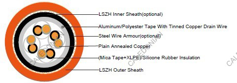
Conductor: Plain annealed copper wire, stranded according to IEC(EN) 60228 class 2.Insulation: Mica glass tape covered by extruded cross-linked XLPE compound or fire resistant silicone rubber compound type EI2 as per BS 7655-1.1.
Cabling Elements: Insulated cores are twisted to form pairs with varying lay length to minimize crosstalk. Two-pair cable had four cores laid in quad formation.
Cabling: Pairs are cabled together.In cables with 8 pairs or more, 4 pairs are assembled to form a bunch, the bunches are then cabled together.
Overall Screen: Aluminum/polyester tape with 0.5mm2 screen (7/0.3mm) tinned copper drain wire.
Inner Sheath(optional):Thermoplastic LSZH compound type LTS3 as per BS 7655-6.1
Armouring(optional): Galvanized steel wire armour
Outer Sheath: Thermoplastic LSZH compound type LTS3 as per BS 7655-6.1(Thermosetting LSZH compound type SW2-SW4 as per BS 7655-2.6 can be offered.)
COLOUR CODE
Insulation Colour: White with black numberings.Sheath Colour: Orange (other colours on request).
TYPE CODE
RE- Instrumentation cable H Halogen free & zero halogen
2X XLPE 2G Silicon Rubber
(St) Static shield of aluminium tape SWA Steel Wire Armoured
FE180 Insulation integrity (950°C 180 minutes) CI Circuit integrity
PH 90 Fire Test for 90 mins at 830°C
Physical AND THERMAL PROPERTIES
Temperature range during operation (fixed state): -30°C – +70°CTemperature range during installation (mobile state): -20°C – +50°C
Minimum bending radius: 6 x Overall Diameter (unarmoured cables with silicone rubber insulation)
8 x Overall Diameter (unarmoured cables with XLPE insulation)
10 x Overall Diameter (armoured cables)
Electrical PROPERTIES
| Dielectric test: | 2000 V r.m.s. x 5' (core/core) |
|---|---|
| Insulation resistance | XLPE: ≥1000 MΩ x km (at 20°C) SR: ≥300 MΩ x km (at 20°C) |
| Short circuit temperature | XLPE: 250°C SR: 350°C |
CONSTRUCTION PARAMETERS
| Conductor | RE-2X(St)H.CI. FE 180 PH30 RE-2G(St)H.CI. FE 180 PH30 | RE-2X(St)HSWAH...CI. FE 180 PH30 RE-2G(St)HSWAH...CI. FE 180 PH30 | ||||||
|---|---|---|---|---|---|---|---|---|
| No. of Core X Cross Section | No./ Nominal Diameter of Strands | Nominal Insulation Thickness | Unarmoured | Armoured | ||||
| Nominal Overall Diameter | Approx. Weight | Diameter Under Armour | Armour Wire Diameter | Nominal Overall Diameter | Approx. Weight | |||
| mm2 | no./mm | mm | mm | kg/km | mm | mm | mm | kg/km |
| 1 Pairs | ||||||||
| 1X2x1.0 | 7/0.43 | 0.6 | 8.0 | 76 | 8.0 | 0.90 | 12.4 | 281 |
| 1X2x1.5 | 7/0.53 | 0.7 | 8.5 | 94 | 8.5 | 0.90 | 13.1 | 332 |
| 1X2x2.5 | 7/0.67 | 0.8 | 10.5 | 130 | 10.5 | 0.90 | 15.1 | 401 |
| 2 Pairs | ||||||||
| 2X2x1.0 | 7/0.43 | 0.6 | 12.4 | 120 | 12.4 | 0.90 | 17.4 | 370 |
| 2X2x1.5 | 7/0.53 | 0.7 | 14.0 | 160 | 14.0 | 0.90 | 18.4 | 450 |
| 2X2x2.5 | 7/0.67 | 0.8 | 16.0 | 230 | 16.0 | 0.90 | 20.5 | 550 |
| 5 Pairs | ||||||||
| 5X2x1.0 | 7/0.43 | 0.6 | 16.5 | 276 | 16.5 | 1.25 | 22 | 854 |
| 5X2x1.5 | 7/0.53 | 0.7 | 20.5 | 368 | 20.5 | 1.25 | 26.2 | 1023 |
| 5X2x2.5 | 7/0.67 | 0.8 | 23.0 | 518 | 23.0 | 1.25 | 28.9 | 1276 |
| 10 Pairs | ||||||||
| 10X2x1.0 | 7/0.43 | 0.6 | 20.5 | 501 | 20.5 | 1.25 | 26.4 | 1271 |
| 10X2x1.5 | 7/0.53 | 0.7 | 26.0 | 673 | 26.0 | 1.60 | 32.8 | 1742 |
| 10X2x2.5 | 7/0.67 | 0.8 | 29.5 | 971 | 29.5 | 1.60 | 36.5 | 2205 |
| 20 Pairs | ||||||||
| 20X2x1.0 | 7/0.43 | 0.6 | 26.5 | 917 | 26.5 | 1.60 | 33.3 | 2197 |
| 20X2x1.5 | 7/0.53 | 0.7 | 34.0 | 1258 | 34.0 | 1.60 | 41.2 | 2705 |
| 20X2x2.5 | 7/0.67 | 0.8 | 38.5 | 1830 | 38.5 | 2.00 | 46.7 | 3836 |
Note : Other conductor sizes & core configurations are available upon request. The parameters listed above are nominal values as per cable standards. Actual values may vary due to material and manufacturing process variations. For precise specifications or customized requirements, please contact us for further information.

