


PRODUCTS
- Aerial Bundled Cables
- Airport Cables
- Automotive Cables
- Alarm & Audio & Electronic Cables
- Belden Equivalent Cables
- Bus Cables
- Cable Glands
- Cables for Oil Industry
- Coaxial Cables
- Composite Cables
- Control Cables
- Data Cable
- Elevator Cables
- Fiber Optic Cables
- Fire Resisting Cable(Fireflix)
- Fire Retardant Cable(FIRETOX)
- Flame Retardant Cable (FIREGUARD)
- Flexible Cables
- Heat Detection Cables
- High Temperature Cables
- Highway Cables
- Industrial Cables
- Instrumentation Cables
- Lan Cables
- Marine Cable
- NEK606 Water Blocked Offshore & Marine Cables
- IEC60092 STANDARD Offshore & Marine Cables
- BS 6883&BS7917 STANDARD Offshore & Marine Cables
- UKOOA Offshore & Marine cables
- VG 95218 Navy Cables
- Mining Cables
- Airframe Wire
- Marine, OIL,GAS & Petrochemical Cables
- Power Cables
- Railway Cables
- Robotics
- Rolling Stock Cables
- Rubber & Crane Cables
- Security Cables
- Special Cables
- Spiral Cables
- Telephone Cables
- Thermocouple Cables
- BS 5308 Cable
- PAS 5308 Cable
- BS 5467 Cable
- BS 6724 Cable
- BS 6346 Cable
- BS 7211 Cable
- IEC 60502-1 Cable
HOT PRODUCTS


APPLICATIONS
|
PAS5308 Part 1 / Type 3 (lead sheath cables)
PAS 5308 Cable Part 1 Type 3 OS-Lead SWA
Application
These cables are designed to connect electrical instrumentation and communication systems in and around process plants and similar applications. Generally used to transmit analogue or digital signals in measurement and process control where chemicals may be present.They are well adapted to underground use in industrial applications, in moist areas, where chemical and mechanical protections are needed. The lead sheath brings an enhanced resistance to aromatic hydrocarbons.
Construction
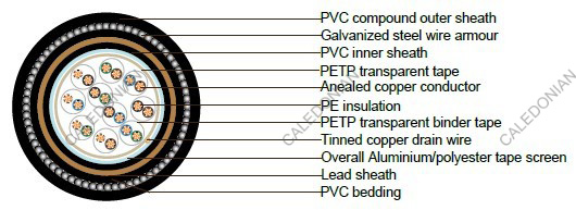
| Conductor | Annealed copper, sizes: 0.5mm² mulitistranded(Class 5), 0.5 mm² and 1.0 mm² solid(Class 1), 1.5mm² or 2.5 multistranded(Class 2) to BS EN 60228 |
|---|---|
| Insulation | thermoplastic PE to BS EN 50290-2-23:2002, grade L/MD or a cross-linked PE to BS EN 50290-2-29 |
| Pairing | Two insulated conductors uniformly twisted together with a lay not exceeding 100mm, Two-pair cables without individual pair screens (quads) shall have four cores laid in quad formation round a central dummy |
| Colour code | See technical information |
| Binder tape | Non-hygroscopic binder tape of minimum thickness 0.023 mm |
| Collective screen | Aluminium/polyester tape is applied over the laid up pairs metallic side down in contact with tinned copper drain wire, 0.5mm² |
| Inner Sheath | Extruded sheath of a PVC compound conforming to BS EN 50290-2-22:2002, grade TM51 |
| Lead Sheath | Lead Alloy conforming to BS EN 50307 |
| Bedding | Extruded sheath of a PVC compound conforming to BS EN 50290-2-22:2002, grade TM51 |
| Amour | Galvanized steel wire armour |
| Outer sheath | extruded sheath of a PVC compound conforming to BS EN 50290-2-22:2002, grade TM51 |
| Sheath colour | Generally black |
Electrical Properties
Temperature range: above 0˚C( fixed installation)
-15˚C to +65˚C(during operation )
| Conductor Area Size | mm² | 0.5 | 0.5 | 1.0 | 1.5 | 2.5 | |
|---|---|---|---|---|---|---|---|
| Conductor Stranding | No. x mm | 1 x 0.8 | 16 x 0.2 | 1 x 1.13 | 7 x 0.53 | 7 x 0.67 | |
| Conductor resistance max | ohm/km | 36.8 | 39.7 | 18.4 | 12.3 | 7.6 | |
| Insulation resistance min | Individual conductor | Gohm/km | 5 | 5 | 5 | 5 | 5 |
| individual screen | Mohm/km | 1 | 1 | 1 | 1 | 1 | |
| Capacitance unbalance at 1 kHz(pair to pair screen) | pF/250m | 250 |
|||||
| Max. Mutual Capacitance @ 1 kHz for Non OS or OS cables (except one-pair and two-pairs) | pF/m | 75 | 75 | 75 | 85 | 105 | |
| Max. Mutual Capacitance @ 1 kHz IS/OS cables (include 1 pair and 2 pair) | pF/m | 115 | 115 | 115 | 120 | 140 | |
| Max. L/R Ratio for adjacent cores(Inductance/Resistance) | μH/ohm | 25 | 25 | 25 | 40 | 60 | |
| Test voltage | V | 2000 | 2000 | 2000 | 2000 | 2000 | |
| Rated voltage | V | 300/500 | 300/500 | 300/500 | 300/500 | 300/500 | |
Parameter
| NO. of Pairs | Thick- ness of Insula- tion | Thick- ness of Inner sheath | Dia- meter over Inner sheath | Thick- ness of Lead Sheath | Dia- meter over Lead Sheath | Thick- ness of Bedding | Dia- meter over Bedding | Thick- ness of Armour | Dia- meter over Armor | Thick- ness of Sheath | Dia- meter of Cable |
|---|---|---|---|---|---|---|---|---|---|---|---|
| mm | mm | mm | mm | mm | mm | mm | mm | mm | mm | mm | |
| solid conductor 0.5mm² (1/0.80mm) | |||||||||||
| 1 | 0.5 | 0.8 | 5.3 | 1.1 | 7.5 | 0.8 | 9.1 | 0.9 | 10.9 | 1.4 | 13.7 |
| 2 | 0.5 | 1.1 | 6.1 | 1.1 | 8.3 | 0.8 | 9.9 | 0.9 | 11.7 | 1.4 | 14.5 |
| 5 | 0.5 | 1.2 | 10.6 | 1.1 | 12.8 | 0.8 | 14.4 | 1.25 | 16.9 | 1.6 | 20.1 |
| 10 | 0.5 | 1.2 | 14 | 1.1 | 16.2 | 1 | 18.2 | 1.6 | 21.4 | 1.7 | 24.8 |
| 15 | 0.5 | 1.2 | 16.1 | 1.2 | 18.5 | 1 | 20.5 | 1.6 | 23.7 | 1.8 | 27.3 |
| 20 | 0.5 | 1.3 | 18.4 | 1.3 | 21 | 1 | 23 | 1.6 | 26.2 | 1.8 | 29.8 |
| 30 | 0.5 | 1.3 | 22 | 1.4 | 24.8 | 1 | 26.8 | 1.6 | 30 | 1.9 | 33.8 |
| 50 | 0.5 | 1.5 | 27.9 | 1.5 | 30.9 | 1.2 | 33.3 | 2 | 37.3 | 2.1 | 41.5 |
| stranded conductor 0.5 mm² (16/0.20mm) | |||||||||||
| 1 | 0.6 | 0.8 | 6 | 1.1 | 8.2 | 0.8 | 9.8 | 0.9 | 11.6 | 1.4 | 14.4 |
| 2 | 0.6 | 0.8 | 6.9 | 1.1 | 9.1 | 0.8 | 10.7 | 0.9 | 12.5 | 1.4 | 15.3 |
| 5 | 0.6 | 1.1 | 12.1 | 1.1 | 14.3 | 0.8 | 15.9 | 1.25 | 18.4 | 1.6 | 21.6 |
| 10 | 0.6 | 1.2 | 16.2 | 1.2 | 18.6 | 1 | 20.6 | 1.6 | 23.8 | 1.8 | 27.4 |
| 15 | 0.6 | 1.3 | 18.8 | 1.3 | 21.4 | 1 | 23.4 | 1.6 | 26.6 | 1.8 | 30.2 |
| 20 | 0.6 | 1.3 | 21.3 | 1.3 | 23.9 | 1 | 25.9 | 1.6 | 29.1 | 1.9 | 32.9 |
| 30 | 0.6 | 1.5 | 25.9 | 1.5 | 28.9 | 1.2 | 31.3 | 2.5 | 35.3 | 2.1 | 39.5 |
| 50 | 0.6 | 1.7 | 32.9 | 1.7 | 36.3 | 1.4 | 39.1 | 2.5 | 44.1 | 2.3 | 48.7 |
| solid conductor 1.0mm² (1/1.13mm) | |||||||||||
| 1 | 0.6 | 0.8 | 6.4 | 1.1 | 8.6 | 0.8 | 10.2 | 0.9 | 12 | 1.4 | 14.8 |
| 2 | 0.6 | 0.8 | 7.4 | 1.1 | 9.6 | 0.8 | 11.2 | 0.9 | 13 | 1.5 | 16 |
| 5 | 0.6 | 1.2 | 13.2 | 1.1 | 15.4 | 1 | 17.4 | 1.6 | 20.6 | 1.7 | 24 |
| 10 | 0.6 | 1.2 | 17.4 | 1.2 | 19.8 | 1 | 21.8 | 1.6 | 25 | 1.8 | 28.6 |
| 15 | 0.6 | 1.3 | 20.3 | 1.3 | 22.9 | 1 | 24.9 | 1.6 | 28.1 | 1.9 | 31.9 |
| 20 | 0.6 | 1.5 | 23.4 | 1.4 | 26.2 | 1.2 | 28.6 | 2 | 32.6 | 2 | 36.6 |
| 30 | 0.6 | 1.5 | 28 | 1.5 | 31 | 1.2 | 33.4 | 2 | 37.4 | 2.1 | 41.6 |
| 50 | 0.6 | 2 | 36.3 | 1.8 | 39.9 | 1.4 | 42.7 | 2.5 | 47.7 | 2.4 | 52.5 |
| stranded conductor 1.5 mm² (7/0.53mm) | |||||||||||
| 1 | 0.6 | 0.8 | 7.3 | 1.1 | 9.5 | 0.8 | 11.1 | 0.9 | 12.9 | 1.5 | 15.9 |
| 2 | 0.6 | 0.9 | 8.7 | 1.1 | 10.9 | 0.8 | 12.5 | 1.25 | 15 | 1.5 | 18 |
| 5 | 0.6 | 1.2 | 15.4 | 1.2 | 17.8 | 1 | 19.8 | 1.6 | 23 | 1.7 | 26.4 |
| 10 | 0.6 | 1.3 | 20.6 | 1.3 | 23.2 | 1 | 25.2 | 1.6 | 28.4 | 1.9 | 32.2 |
| 15 | 0.6 | 1.5 | 24.2 | 1.4 | 27 | 1.2 | 29.4 | 2 | 33.4 | 2 | 37.4 |
| 20 | 0.6 | 1.5 | 27.5 | 1.5 | 30.5 | 1.2 | 32.9 | 1.6 | 36.9 | 2.1 | 41.1 |
| 30 | 0.6 | 1.7 | 33.3 | 1.7 | 36.7 | 1.4 | 39.5 | 2.5 | 44.5 | 2.3 | 49.1 |
| 50 | 0.6 | 2 | 42.6 | 2 | 46.6 | 1.6 | 49.8 | 2.5 | 54.8 | 2.6 | 60 |
| stranded conductor 2.5 mm² (7/0.67mm) | |||||||||||
| 1 | 0.6 | 0.8 | 8.1 | 1.1 | 10.3 | 0.8 | 11.9 | 1.25 | 14.4 | 1.5 | 17.4 |
| 2 | 0.6 | 0.9 | 9.7 | 1.1 | 11.9 | 0.8 | 13.5 | 1.25 | 16 | 1.5 | 19 |
| 5 | 0.6 | 1.2 | 17.2 | 1.2 | 19.6 | 1 | 21.6 | 1.6 | 24.8 | 1.8 | 28.4 |
| 10 | 0.6 | 1.4 | 24.1 | 1.4 | 26.9 | 1.2 | 29.3 | 2 | 33.3 | 2 | 37.3 |
| 15 | 0.6 | 1.6 | 28.2 | 1.5 | 31.2 | 1.2 | 33.6 | 2 | 37.6 | 2.2 | 42 |
| 20 | 0.6 | 1.7 | 31.8 | 1.7 | 35.2 | 1.4 | 38 | 2.5 | 43 | 2.3 | 47.6 |
| 30 | 0.6 | 1.9 | 37.9 | 1.8 | 41.5 | 1.4 | 44.3 | 2.5 | 49.3 | 2.5 | 54.3 |
| 50 | 0.6 | 2.3 | 48.9 | 2.2 | 53.3 | 1.6 | 56.5 | 2.5 | 61.5 | 2.8 | 67.1 |
© 2021 Caledonian cables

