BS5308 Part 2 / Type 2
BS5308 Cable Part 2 Type 2 PVC-IS-OS-SWA-PVC
Application
The armoured versions (Part 2 Type 2) are generally used when the risk of mechanical damage is increased. The galvanised steel wire armour provides excellent protection. Generally used within industrial process anufacturing plants for communication, data and voice transmission signals and services, Also used for the interconnection of electrical equipment and instruments, typically in chemical or petrolchemical industry. The armored versions are generally use for outdoor installation for direct burial or installed in the duct and suitable for wet and damp areas.
Construction
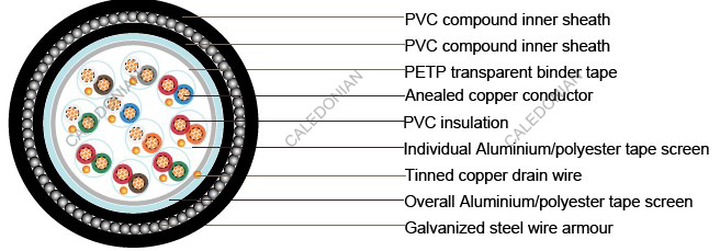
| Conductor |
Annealed copper, sizes: 0.5mm² and 0.75mm² mulitistranded(Class 5), 1.5mm² multistranded(Class 2) to BS6360 |
| Insulation |
PVC (polyvinyl chloride),type TI1 to BS 6746 |
| Pairing |
Two insulated conductors uniformly twisted together with a lay not exceeding 100mm |
| Colour code |
Multipair cables:See technical information |
| Individual screen |
Aluminium/polyester tape is applied over each pair metallic side down in contact with tinned copper drain wire, 0.5mm² |
| Binder tape |
PETP transparent tape |
| Collective screen |
Aluminium/polyester tape is applied over the laid up pairs metallic side down in contact with tinned copper drain wire, 0.5mm² |
| Inner Sheath |
PVC (polyvinyl chloride), type TM 1 to BS 6746 |
| Amour |
Galvanized steel wire armour |
| Outer sheath |
PVC Sheath, type TM 1 or type 6 to BS 6746 |
| Sheath colour |
Black or blue |
Mechanical and Electrical Properties
Operating temperature: -40˚C up to + 70˚C( fixed installation) 0˚C to +50˚C(during operation )
Minimum bending radius: 6 x overall diameter
| Conductor Area Size |
mm2 |
0.5 |
0.75 |
1.5 |
| Conductor Stranding |
No. x mm |
16 x 0.2 |
24 x 0.2 |
7 x 0.53 |
| Conductor resistance max |
ohm/km |
39.7 |
26.5 |
12.3 |
| Insulation resistance min |
Mohm/km |
25 |
25 |
25 |
| Max. Mutual Capacitance:pair or adjacent cores |
pF/m |
250 |
250 |
250 |
| Capacitance between any core or screen max. |
pF/m |
400 |
400 |
400 |
| Max. L/R Ratio for adjacentcores(Inductance/Resistance) |
μH/ohm |
25 |
25 |
40 |
| Test voltage |
Core to core |
V |
1000 |
1000 |
1000 |
| Core to screen |
V |
1000 |
1000 |
1000 |
| Rated voltage max |
V |
300/500 |
300/500 |
300/500 |
Parameter
| No.of pairs |
No.and Dia. of Wires |
Nominal Conductor Cross-Sectional Area |
Nominal Thickness of Insulation |
Nominal Thickness of bedding |
Nominal Dia. over Bedding |
Nominal Thickness of Armour |
Nominal Thickness of Sheath |
Nominal Dia. of Cable |
Approx. Weight |
|
no./mm |
mm2 |
mm |
mm |
mm |
mm |
mm |
mm |
kg/km |
| 2 |
16/0.2 |
0.5 |
0.6 |
0.8 |
10.6 |
0.9 |
1.3 |
15 |
505 |
| 5 |
16/0.2 |
0.5 |
0.6 |
1.1 |
14.3 |
0.9 |
1.5 |
19.1 |
830 |
| 10 |
16/0.2 |
0.5 |
0.6 |
1.2 |
19.1 |
1.25 |
1.6 |
24.8 |
1420 |
| 15 |
16/0.2 |
0.5 |
0.6 |
1.3 |
22.2 |
1.6 |
1.7 |
28.8 |
1570 |
| 20 |
16/0.2 |
0.5 |
0.6 |
1.3 |
25.3 |
1.6 |
1.8 |
32.1 |
2040 |
| 30 |
16/0.2 |
0.5 |
0.6 |
1.5 |
30.6 |
1.6 |
1.9 |
37.6 |
2610 |
| 50 |
16/0.2 |
0.5 |
0.6 |
1.7 |
38.9 |
2 |
2.1 |
47.1 |
4270 |
| 2 |
24/0.2 |
0.75 |
0.6 |
0.8 |
11.5 |
0.9 |
1.4 |
16.1 |
545 |
| 5 |
24/0.2 |
0.75 |
0.6 |
1.2 |
15.7 |
1.25 |
1.5 |
21.2 |
1005 |
| 10 |
24/0.2 |
0.75 |
0.6 |
1.3 |
20.9 |
1.6 |
1.7 |
27.5 |
1400 |
| 15 |
24/0.2 |
0.75 |
0.6 |
1.3 |
24.2 |
1.6 |
1.8 |
31 |
1750 |
| 20 |
24/0.2 |
0.75 |
0.6 |
1.5 |
27.9 |
1.6 |
1.8 |
34.7 |
2300 |
| 30 |
24/0.2 |
0.75 |
0.6 |
1.7 |
33.8 |
2 |
2 |
41.8 |
2460 |
| 50 |
24/0.2 |
0.75 |
0.6 |
2 |
43.1 |
2.5 |
2.3 |
52.7 |
4800 |
| 2 |
7/0.53 |
1.5 |
0.6 |
0.9 |
13 |
0.9 |
1.4 |
17.6 |
800 |
| 5 |
7/0.53 |
1.5 |
0.6 |
1.2 |
17.5 |
1.25 |
1.6 |
23.2 |
1290 |
| 10 |
7/0.53 |
1.5 |
0.6 |
1.3 |
23.5 |
1.6 |
1.8 |
30.3 |
1990 |
| 15 |
7/0.53 |
1.5 |
0.6 |
1.5 |
27.6 |
1.6 |
1.9 |
34.6 |
2590 |
| 20 |
7/0.53 |
1.5 |
0.6 |
1.5 |
31.3 |
1.6 |
2 |
38.5 |
3310 |
| 30 |
7/0.53 |
1.5 |
0.6 |
1.7 |
38 |
2 |
2.1 |
46.2 |
4380 |
| 50 |
7/0.53 |
1.5 |
0.6 |
2 |
48.5 |
2.5 |
2.4 |
58.3 |
6260 |


