BS5308 Part 1 / Type 1 (unarmoured cables)
BS5308 Cable Part 1 Type 2
PE-OS-Lead-SWA-PVC
Application
The armoured versions (Part 1 Type 3) are generally used when the risk of mechanical damage is increased. The galvanised steel wire armour provides excellent protection. Generally used within industrial process anufacturing plants for communication, data and voice transmission signals and services, Also used for the interconnection of electrical equipment and instruments, typically in petroleum industry. They are well adapted to underground use in industrial applications, in moist areas, where chemical and mechanical protections are needed. The lead heath brings an enhanced resistance to aromatic hydrocarbons.
Construction
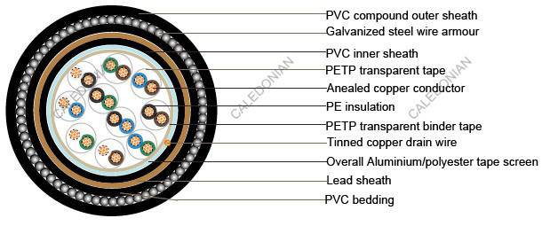
| Conductor |
Annealed copper, sizes: 0.5mm² and 0.75mm² mulitistranded(Class 5), 0.5 mm², 1.0 mm² solid(Class 1), 1.5mm² or 2.5mm², multistranded(Class 2) to BS6360 |
| Insulation |
PE (Polyethylene) type 03 to BS6234 |
| Pairing |
Two insulated conductors uniformly twisted together with a lay not exceeding 100mm |
| Colour code |
See technical information |
| Binder tape |
PETP transparent tape |
| Collective screen |
Aluminium/polyester tape is applied over the laid up pairs metallic side down in contact with tinned copper drain wire, 0.5mm² |
| Inner Sheath |
PVC (polyvinyl chloride), type TM 1 or type 6 toBS 6746 |
| Lead Sheath |
Lead Alloy |
| Bedding |
PVC (polyvinyl chloride), TM 1 to BS 6746 |
| Amour |
Galvanized steel wire armour |
| Outer sheath |
PVC Sheath, type TM 1 or type 6 to BS 6746 |
| Sheath colour |
Black or blue |
Mechanical and Electrical Properties
Operating temperature: -40˚C up to + 70˚C( fixed installation) 0˚C to +50˚C(during operation )
Minimum bending radius: 15 x overall diameter
| Conductor Area Size |
mm2 |
0.5 |
0.5 |
0.75 |
1.0 |
1.5 |
| Conductor Stranding |
No. x mm |
1 x 0.8 |
16 x 0.2 |
24 x 0.2 |
1 x 1.13 |
7 x 0.53 |
| Conductor resistance max |
ohm/km |
36.8 |
39.7 |
26.5 |
18.2 |
12.3 |
| Insulation resistance min |
Gohm/km |
5 |
5 |
5 |
5 |
5 |
| Capacitance unbalance at 1kHz(pair to pair screen) |
pF/250m |
|
|
250 |
|
|
| Max. Mutual Capacitance@ 1 kHz forNon OS or OScables (except one-pair andtwo-pairs) |
pF/m |
75 |
75 |
75 |
75 |
85 |
| Max. Mutual Capacitance @1 kHz IS/OS cables (include1 pair and 2 pair) |
pF/m |
115 |
115 |
115 |
115 |
120 |
| Max. L/R Ratio for adjacentcores(Inductance/Resistance) |
μH/ohm |
25 |
25 |
25 |
25 |
40 |
| Test voltage |
Core to core |
V |
1000 |
1000 |
1000 |
1000 |
1000 |
| Core to screen |
V |
1000 |
1000 |
1000 |
1000 |
1000 |
| Rated voltage max |
V |
300/500 |
300/500 |
300/500 |
300/500 |
300/500 |
| No.of Pairs |
No.and Dia. of Wires |
Nominal Conductor Cross-Sectional Area |
Nominal Thickness of Insulation |
Nominal Dia. over Bedding |
Nominal Thickness of Armour |
Nominal Dia. of Cable |
Approx. Weight |
| no./mm |
mm2 |
mm |
mm |
mm |
mm |
kg/km |
| 1 |
1/0.80 |
0.5 |
0.5 |
6.3 |
0.9 |
10.7 |
200 |
| 2 |
1/0.80 |
0.5 |
0.5 |
7.1 |
0.9 |
11.5 |
260 |
| 5 |
1/0.80 |
0.5 |
0.5 |
11.6 |
0.9 |
16.2 |
460 |
| 10 |
1/0.80 |
0.5 |
0.5 |
15 |
1.25 |
20.7 |
790 |
| 15 |
1/0.80 |
0.5 |
0.5 |
17.1 |
1.25 |
22.8 |
1100 |
| 20 |
1/0.80 |
0.5 |
0.5 |
19.4 |
1.6 |
26 |
1280 |
| 30 |
1/0.80 |
0.5 |
0.5 |
23 |
1.6 |
29.8 |
1520 |
| 50 |
1/0.80 |
0.5 |
0.5 |
28.9 |
1.6 |
26.1 |
2100 |
| 1 |
16/0.20 |
0.5 |
0.6 |
7 |
0.9 |
11.4 |
250 |
| 2 |
16/0.20 |
0.5 |
0.6 |
7.9 |
0.9 |
12.3 |
300 |
| 5 |
16/0.20 |
0.5 |
0.6 |
13.1 |
0.9 |
17.9 |
560 |
| 10 |
16/0.20 |
0.5 |
0.6 |
17.2 |
1.25 |
22.9 |
970 |
| 15 |
16/0.20 |
0.5 |
0.6 |
19.8 |
1.6 |
26.4 |
1240 |
| 20 |
16/0.20 |
0.5 |
0.6 |
22.3 |
1.6 |
29.1 |
1640 |
| 30 |
16/0.20 |
0.5 |
0.6 |
26.9 |
1.6 |
33.9 |
1770 |
| 50 |
16/0.20 |
0.5 |
0.6 |
33.9 |
2 |
42.1 |
2770 |
| 1 |
1/1.13 |
1 |
0.6 |
7.4 |
0.9 |
11.8 |
290 |
| 2 |
1/1.13 |
1 |
0.6 |
8.4 |
0.9 |
13 |
345 |
| 5 |
1/1.13 |
1 |
0.6 |
14.2 |
1.25 |
19.7 |
790 |
| 10 |
1/1.13 |
1 |
0.6 |
17.4 |
1.25 |
24.3 |
1310 |
| 15 |
1/1.13 |
1 |
0.6 |
21.3 |
1.6 |
28.1 |
1740 |
| 20 |
1/1.13 |
1 |
0.6 |
24.4 |
1.6 |
31.2 |
2040 |
| 30 |
1/1.13 |
1 |
0.6 |
29 |
1.6 |
36.2 |
2180 |
| 50 |
1/1.13 |
1 |
0.6 |
37.3 |
2 |
45.7 |
3500 |
| 1 |
7/0.53 |
1.5 |
0.6 |
8.3 |
0.9 |
12.9 |
320 |
| 2 |
7/0.53 |
1.5 |
0.6 |
9.7 |
0.9 |
14.3 |
420 |
| 5 |
7/0.53 |
1.5 |
0.6 |
16.4 |
1.25 |
22.1 |
940 |
| 10 |
7/0.53 |
1.5 |
0.6 |
21.6 |
1.6 |
28.4 |
1500 |
| 15 |
7/0.53 |
1.5 |
0.6 |
25.2 |
1.6 |
32.2 |
1970 |
| 20 |
7/0.53 |
1.5 |
0.6 |
28.5 |
2 |
36.5 |
2400 |
| 30 |
7/0.53 |
1.5 |
0.6 |
34.3 |
2 |
42.5 |
3170 |
| 50 |
7/0.53 |
1.5 |
0.6 |
43.6 |
2.5 |
53.4 |
5020 |


