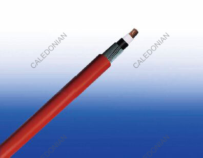
600/1000V XLPE Insulated, LSZH Sheathed Armoured CPR approved Power Cables to IEC 60502-1(Single Core)
FTX300 1RZ1MAZ1-R (CU/XLPE/LSZH/AWA/LSZH 600/1000V Class 2)


Applications
IEC 60502-1 600/1000V XLPE Insulated, LSZH Sheathed CPR approved Power Cables are mainly used in power stations, mass transit underground passenger systems, airports,
petrochemical plants, hotels, hospitals and high-rise buildings..
Standard
Basic design to IEC 60502-1
FIRE PERFORMANCE
| Flame Retardance (Single vertical wire or cable test) |
IEC 60332-1-2; EN 60332-1-2 |
| Reduced Fire Propagation (Vertically-mounted bundled wires & cables test) |
IEC 60332-3-24; EN 60332-3-24 |
| Halogen Free |
IEC 60754-1; EN 50267-2-1 |
| No Corrosive Gas Emission |
IEC 60754-2; EN 50267-2-2 |
| Minimum Smoke Emission |
IEC 61034-2; EN 61034-2 |
| CPR Compliance |
Eca |
Voltage Rating
600/1000V
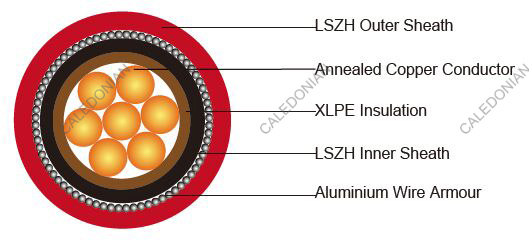
Construction
| Conductor |
The conductors shall be class 2 plain or metal-coated annealed copper in accordance with IEC
60228. Class 1 and class 5 conductor can be offered as option. |
| Insulation |
Thermosetting XLPE compound as per IEC 60502-1. |
| Inner Covering Option: |
Thermoplastic halogen free compound ST8 as per IEC 60502-1. |
| Armouring: |
Aluminium wire. |
| Outer Sheath: |
Thermoplastic halogen free compound ST8 as per IEC 60502-1. |
| Outer Sheath Option |
UV resistance, hydrocarbon resistance, oil resistance, anti-rodent and anti-termite
properties can be offered as option. |
Colour Code
| Insulation Colour |
Brown or blue; other colours can be offered upon request. |
| Sheath Colour |
Black; other colours can be offered upon request. |
PHYSICAL AND THERMAL PROPERTIES
| Maximum temperature range during operation: |
90°C |
| Maximum short circuit temperature (5 Seconds): |
250°C |
| Minimum bending radius: |
6 × Overall Diameter |
CONSTRUCTION PARAMETERS
| Conductor |
FTX300 1RZ1MAZ1-R |
| No. of Cores × Cross-sectional Area |
Conductor Class |
Nominal Insulation Thickness |
Nominal Inner Covering Thickness |
Nominal AL Wire Diameter |
Nominal Sheath Thickness |
Approx. Overall Diameter |
Approx. Weight |
| No.×mm² |
|
mm |
mm |
mm |
mm |
mm |
kg/km |
| 1×4 |
2 |
0.7 |
1.0 |
0.8 |
1.8 |
11.2 |
200 |
| 1×6 |
2 |
0.7 |
1.0 |
0.8 |
1.8 |
11.7 |
233 |
| 1×10 |
2 |
0.7 |
1.0 |
0.8 |
1.8 |
12.7 |
294 |
| 1×16 |
2 |
0.7 |
1.0 |
0.8 |
1.8 |
13.7 |
377 |
| 1×25 |
2 |
0.9 |
1.0 |
0.8 |
1.8 |
15.4 |
513 |
| 1×35 |
2 |
0.9 |
1.0 |
1.25 |
1.8 |
17.5 |
688 |
| 1×50 |
2 |
1.0 |
1.0 |
1.25 |
1.8 |
19.0 |
856 |
| 1×70 |
2 |
1.1 |
1.0 |
1.25 |
1.8 |
21.0 |
1124 |
| 1×95 |
2 |
1.1 |
1.0 |
1.6 |
1.8 |
24.0 |
1521 |
| 1×120 |
2 |
1.2 |
1.0 |
1.6 |
1.8 |
25.8 |
1831 |
| 1×150 |
2 |
1.4 |
1.0 |
1.6 |
1.8 |
27.8 |
2176 |
| 1×185 |
2 |
1.6 |
1.0 |
1.6 |
1.8 |
30.4 |
2668 |
| 1×240 |
2 |
1.7 |
1.0 |
1.6 |
1.9 |
33.5 |
3367 |
| 1×300 |
2 |
1.8 |
1.0 |
2.0 |
2.0 |
37.5 |
4241 |
| 1×400 |
2 |
2.0 |
1.2 |
2.0 |
2.2 |
41.3 |
5283 |
| 1×500 |
2 |
2.2 |
1.2 |
2.0 |
2.3 |
45.4 |
6535 |
Note: The parameters listed above are nominal values as per cable standards. Actual values may vary due to material and manufacturing process variations. For precise specifications or customized requirements, please contact us for further information.
Electrical Properties
| Conductor Operating Temperature |
90°C |
| Ambient Temperature |
30°C |
Current-Carrying Capacities (Amp) according to BS 7671:2008 table 4E3A
| Conductor cross- sectional area |
Ref. Method C (clipped direct) |
Ref. Method F
(in free air or on a perforated cable tray, horizontal or vertical) |
| Touching |
Touching |
Spaced by on cable diameter |
| 2
cables,
singlephase
a.c. or
d.c. flat |
3 or 4
cables,
threephase
a.c. flat |
2
cables,
singlephase
a.c. or
d.c. flat |
3 or 4
cables,
threephase
a.c. flat |
3
cables
threephase
a.c.
trefoil |
2 cables,
d.c. |
2 cables,
single-phase
a.c. |
3 or 4 cables,
three-phase
a.c. |
| Horizontal |
Vertical |
Horizontal |
Vertical |
Horizontal |
Vertical |
| 1 |
2 |
3 |
4 |
5 |
6 |
7 |
8 |
9 |
10 |
11 |
12 |
| mm2 |
A |
A |
A |
A |
A |
A |
A |
A |
A |
A |
A |
| 50 |
237 |
220 |
253 |
232 |
222 |
284 |
270 |
282 |
266 |
288 |
266 |
| 70 |
303 |
277 |
322 |
293 |
285 |
356 |
349 |
357 |
337 |
358 |
331 |
| 95 |
367 |
333 |
389 |
352 |
346 |
446 |
426 |
436 |
412 |
425 |
393 |
| 120 |
425 |
383 |
449 |
405 |
402 |
519 |
497 |
504 |
477 |
485 |
449 |
| 150 |
488 |
437 |
516 |
462 |
463 |
600 |
575 |
566 |
539 |
549 |
510 |
| 185 |
557 |
496 |
587 |
524 |
529 |
688 |
660 |
643 |
614 |
618 |
574 |
| 240 |
656 |
579 |
689 |
612 |
625 |
815 |
782 |
749 |
714 |
715 |
666 |
| 300 |
755 |
662 |
792 |
700 |
720 |
943 |
906 |
842 |
805 |
810 |
755 |
| 400 |
853 |
717 |
899 |
767 |
815 |
1137 |
1094 |
929 |
889 |
848 |
797 |
| 500 |
962 |
791 |
1016 |
851 |
918 |
1314 |
1266 |
1032 |
989 |
923 |
871 |
Voltage Drop (Per Amp Per Meter) according to BS 7671:2008 table 4E3B
| Conductor cross- sectional area |
2
cables d.c. |
Ref. Methods C&F (clipped direct, on trays or in free air) |
| 2 cables, single-phase a.c. |
3 or 4 cables, three-phase a.c. |
| Touching |
Spaced* |
Trefoil and touching |
Flat and touching |
Flat and spaced* |
| 1 |
2 |
3 |
4 |
5 |
6 |
7 |
| mm2 |
mV/A/m |
mV/A/m |
mV/A/m |
mV/A/m |
mV/A/m |
mV/A/m |
| |
|
r |
x |
z |
r |
x |
z |
r |
x |
z |
r |
x |
z |
r |
x |
z |
| 50 |
0.98 |
0.99 |
0.21 |
1.00 |
0.98 |
0.29 |
1.00 |
0.86 |
0.180 |
0.87 |
0.84 |
0.25 |
0.88 |
0.84 |
0.33 |
0.90 |
| 70 |
0.67 |
0.68 |
0.20 |
0.71 |
0.69 |
0.29 |
0.75 |
0.59 |
0.170 |
0.62 |
0.60 |
0.25 |
0.65 |
0.62 |
0.32 |
0.70 |
| 95 |
0.49 |
0.51 |
0.195 |
0.55 |
0.53 |
0.28 |
0.60 |
0.44 |
0.170 |
0.47 |
0.46 |
0.24 |
0.52 |
0.49 |
0.31 |
0.58 |
| 120 |
0.39 |
0.41 |
0.190 |
0.45 |
0.43 |
0.27 |
0.51 |
0.35 |
0.165 |
0.39 |
0.38 |
0.34 |
0.44 |
0.41 |
0.30 |
0.51 |
| 150 |
0.31 |
0.33 |
0.185 |
0.38 |
0.36 |
0.27 |
0.45 |
0.29 |
0.160 |
0.33 |
0.31 |
0.23 |
0.39 |
0.34 |
0.39 |
0.45 |
| 185 |
0.25 |
0.27 |
0.185 |
0.33 |
0.30 |
0.26 |
0.40 |
0.23 |
0.160 |
0.28 |
0.26 |
0.23 |
0.34 |
0.29 |
0.29 |
0.41 |
| 240 |
0.195 |
0.21 |
0.180 |
0.28 |
0.24 |
0.26 |
0.35 |
0.180 |
0.155 |
0.24 |
0.21 |
0.22 |
0.30 |
0.24 |
0.28 |
0.37 |
| 300 |
0.155 |
0.17 |
0.175 |
0.25 |
0.195 |
0.25 |
0.32 |
0.145 |
0.150 |
0.21 |
0.170 |
0.22 |
0.28 |
0.20 |
0.27 |
0.34 |
| 400 |
0.115 |
0.145 |
0.170 |
0.22 |
0.180 |
0.24 |
0.30 |
0.125 |
0.150 |
0.195 |
0.160 |
0.21 |
0.27 |
0.20 |
0.27 |
0.33 |
| 500 |
0.093 |
0.125 |
0.170 |
0.21 |
0.165 |
0.24 |
0.29 |
0.105 |
0.145 |
0.180 |
0.145 |
0.20 |
0.25 |
0.190 |
0.24 |
0.31 |
Note: *Spacings larger than one cable diameter will result in a large voltage drop.
r = conductor resistance at operating temperature
x = reactance
z = impedance