

PRODUCTS
- Aerial Bundled Cables
- Airport Cables
- Automotive Cables
- Alarm & Audio & Electronic Cables
- Belden Equivalent Cables
- Bus Cables
- Cable Glands
- Cables for Oil Industry
- Coaxial Cables
- Composite Cables
- Control Cables
- Data Cables
- Elevator Cables
- Fiber Optic Cables
- Fire Resisting Cable(Fireflix)
- Fire Retardant Cable(FIRETOX)
- Flame Retardant Cable (FIREGUARD)
- Flexible Cables
- Heat Detection Cables
- High Temperature Cables
- Highway Cables
- Industrial Cables
- Instrumentation Cables
- Marine Cable
- NEK606 Water Blocked Offshore & Marine Cables
- IEC60092 STANDARD Offshore & Marine Cables
- BS 6883&BS7917 STANDARD Offshore & Marine Cables
- UKOOA Offshore & Marine cables
- VG 95218 Navy Cables
- Mining Cables
- Airframe Wire
- Marine, OIL,GAS & Petrochemical Cables
- Power Cables
- Railway Cables
- Robotics
- Rolling Stock Cables
- Rubber & Crane Cables
- Security Cables
- Special Cables
- Spiral Cables
- Telephone Cables
- Thermocouple Cables
- BS 5308 Cable
- PAS 5308 Cable
- BS 5467 Cable
- BS 6724 Cable
- BS 6346 Cable
- BS 7211 Cable
- IEC 60502-1 Cable
HOT PRODUCTS

APPLICATIONS
|
Fire Resistant Power & Control Cables
300/500V SR Insulated Control Cables (2-4 Cores)
FFX200 05SZ1-U (PH60) (CU/SR/LSZH 300/500V Class 1)
APPLICATION
The 300/500V SR Insulated Fire Resistant Control Cables are designed, for use as control cable for emergency services and fire circuit control.STANDARDS
Basic design to BS 7629-1FIRE PERFORMANCE
| Circuit Integrity | IEC 60331-21; BS 6387 CWZ; DIN VDE 0472-814(FE180); BS 8434-1 (30mins); BS 5839-1 Clause 26 2d; CEI 20-36/2-1; SS229-1; NBN C 30-004 (cat. F3); NF C32-070-2.3(CR1) |
|---|---|
| Circuit Integrity with mechanical shock | EN 50200(PH60); CEI 20-36/4-0 |
| Circuit Integrity with mechanical shock & water spray | EN 50200 annex E |
| System circuit integrity | DIN 4102-12, E30 depending on lay system |
| Flame Retardance (Single Vertical Wire Test) | EN 60332-1-2; IEC 60332-1-2; BS EN 60332-1-2; VDE 0482-332-1 ; NBN C 30-004 (cat. F1); NF C32-070- 2.1(C2); CEI 20-35/1-2; EN 50265-2-1*; DIN VDE 0482-265-2-1* |
| Reduced Fire Propagation (Vertically-mounted bundled wires & cable test) | EN 60332-3-24 (cat. C); IEC 60332-3-24; BS EN 60332-3-24; VDE 0482-332-3; NBN C 30-004 (cat. F2); NF C32-070-2.2(C1); CEI 20-22/3-4; EN 50266-2-4*; DIN VDE 0482-266-2-4 |
| Halogen Free | IEC 60754-1; EN 50267-2-1; DIN VDE 0482-267-2-1; CEI 20-37/2-1 ; BS 6425-1* |
| No Corrosive Gas Emission | IEC 60754-2; EN 50267-2-2; DIN VDE 0482-267-2-2; CEI 20-37/2-2 ; BS 6425-2* |
| Minimum Smoke Emission | IEC 61034-1&2; EN 61034 -1&2; DIN VDE 0482-1034-1&2; CEI 20-37/3-1&2; EN 50268-1&2*; BS 7622-1&2* |
| No Toxic gases | NES 02-713; NF C 20-454 |
Note: Asterisk * denotes superseded standard.
VOLTAGE RATING
300/500 VCABLE CONSTRUCTION
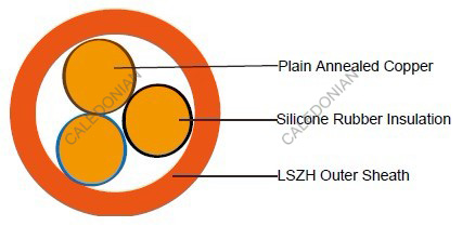
Conductors: Plain annealed copper wire, solid according to IEC(EN) 60228 class 1.Insulation: Fire resistant silicone rubber compound type EI2 as per BS 7655-1.1.
Cabling: The cores are cabled together in concentric layers with suitable non-hygroscopic fillers.
Outer Sheath: Thermoplastic LSZH compound type LTS3 as per BS 7655-6.1 (Thermosetting LSZH
compound type SW2-SW4 as per BS 7655-2.6 can be offered.)
COLOUR CODE
Insulation ColourWithout earth conductor
2 cores black - blue
3 cores black - blue - brown
4 cores black - blue - brown - black
With earth conductor
3 cores black - blue - yellow/green
4 cores black - blue - brown - yellow/green
Sheath Colour: Orange (other colors upon request)
Physical AND THERMAL PROPERTIES
Temperature range during operation (fixed state): -30°C – +90°CTemperature range during installation (mobile state): -20°C – +50°C
Minimum bending radius: 6 x Overall Diameter
Electrical PROPERTIES
| Dielectric test: | 2000 V r.m.s. x 5' (core/core) |
|---|---|
| Insulation resistance | ≥300 MΩ x km (at 20°C) |
| Short circuit temperature | 350°C |
CONSTRUCTION PARAMETERS
| Cable Code | No. of Core X Cross Section | Nominal Insulation Thickness | Nominal Sheath Thickness | Nominal Overall Diameter | Approx. Weight |
|---|---|---|---|---|---|
| mm2 | mm | mm | mm | kg/km | |
| 2 core | |||||
| FFX200 05SZ1-U (PH60) | 2x1.5 | 0.7 | 0.9 | 7.4 | 70 |
| FFX200 05SZ1-U (PH60) | 2x2.5 | 0.8 | 1.0 | 8.8 | 105 |
| 3 core | |||||
| FFX200 05SZ1-U (PH60) | 3x1.5 | 0.7 | 0.9 | 7.9 | 93 |
| FFX200 05SZ1-U (PH60) | 3x2.5 | 0.8 | 1.0 | 9.4 | 141 |
| 4 core | |||||
| FFX200 05SZ1-U (PH60) | 4x1.5 | 0.7 | 1.0 | 8.8 | 122 |
| FFX200 05SZ1-U (PH60) | 4x2.5 | 0.8 | 1.1 | 10.4 | 183 |
Electrical PROPERTIES
Conductor Operating Temperature : 90°CAmbient Temperature : 30°C
Current-Carrying Capacities (Amp)
| Conductor crosssection area | Reference Method 4 (enclosed in an conduit insulated wall etc) | Reference Method 3 (enclosed in conduit on a wall or ceiling, or in trunking) | Reference Method 1 (clipped direct) | Reference Method 11 (on a perforated cable tray), or Reference Method | |||
|---|---|---|---|---|---|---|---|
| one 3-core cable or one 4-core cable 3-phase a.c. | one 2-core cable single phase a.c. or d.c. | one 3-core cable or one 4-core cable 3-phase a.c. | one 2-core cable singlephase a.c. or d.c. | one 3-core cable or one 4-core cable 3-phase a.c. | one 2-core cable single phase a.c. or d.c. | one 3-core cable or one 4-core cable 3-phase a.c. | |
| 1 | 2 | 3 | 4 | 5 | 6 | 7 | 8 |
| mm2 | A | A | A | A | A | A | A |
| 1.5 | 16.5 | 22 | 19.5 | 24 | 22 | 26 | 23 |
| 2.5 | 22 | 30 | 26 | 33 | 30 | 36 | 32 |
Voltage Drop (Per Amp Per Meter)
| Nominal Cross Section Area | 2-core cable d.c. | 2-core cable single- phase a.c | 3-core or 4-core cable 3-phase a.c. |
|---|---|---|---|
| 1 | 2 | 3 | 4 |
| mm2 | mV/A/m | mV/A/m | mV/A/m |
| 1.5 | 31 | 31 | 27 |
| 2.5 | 19 | 19 | 16 |